3.3. Machines
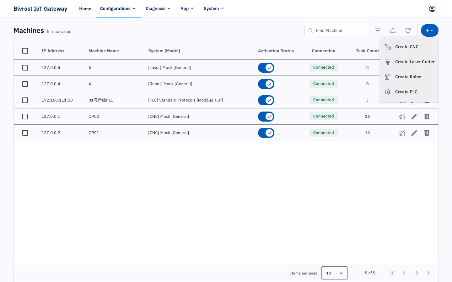
The Machines page is where you configure the machines you want to collect data from.
After changing anything on the Machines page, go back to Home and click Restart Service to apply the changes.
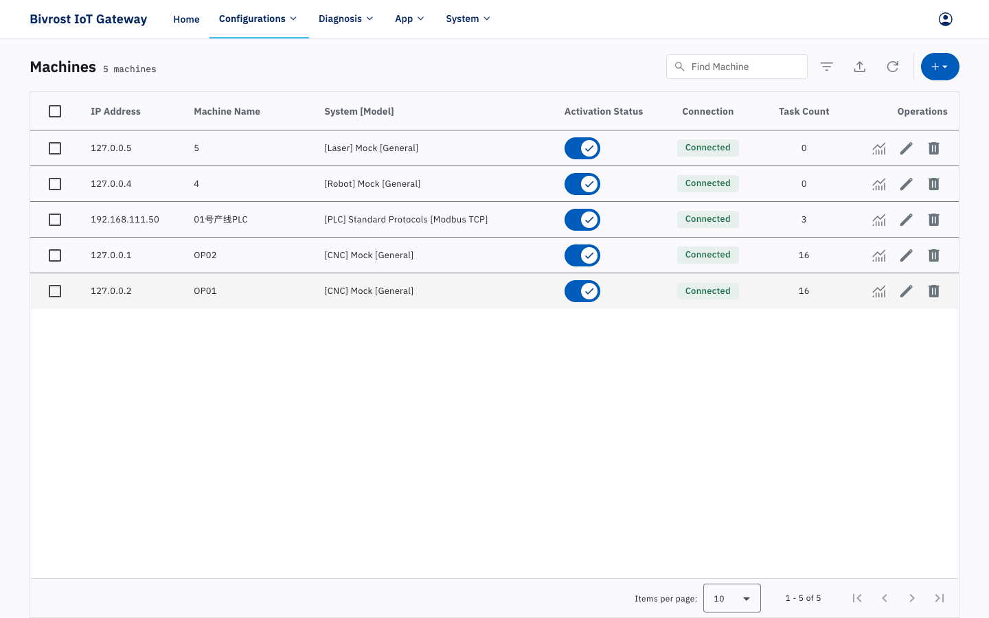
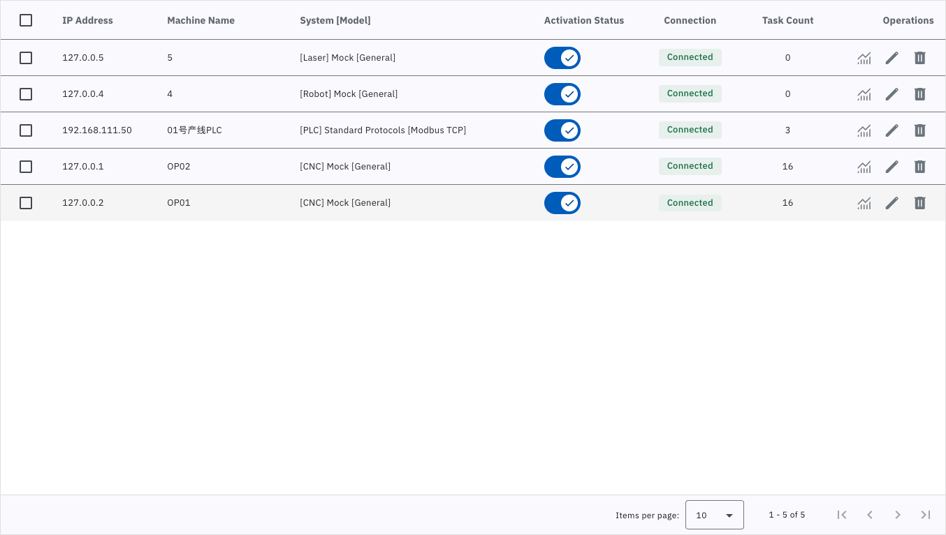
The table on this page lists the IP address, machine name, system model, connection status and task count of every configured machine. A green check in the Connection column means communication is working; any other icon indicates a problem. Hover over the icon to see an explanation, or refer to the table of common connection icons below. Task Count is the number of automatic collection tasks enabled for that machine.
Common connection icons:
| Icon | Meaning |
|---|---|
| ✅ Green check | Communication successful. |
| 🚫 Red no-entry | Unactivated. If activation fails in the create/edit machine dialog, the likely causes are: 1. the license type does not match the machine type; 2. the number of activated machines has reached the licensed maximum. |
| 🔄 Yellow circle | Machine not loaded. Likely causes: 1. the gateway is waiting for the result of the first communication attempt after a service restart, which normally takes up to 10 seconds; 2. the machine was activated but the service has not been restarted. |
| 🔗 Broken link | Machine offline. Likely causes: 1. the machine is powered off; 2. the network is not connected; 3. the machine configuration is wrong; 4. the network settings on the machine are incomplete. |
| ❌ Red cross | Task not ready. Likely causes: 1. the machine configuration is wrong (for example the wrong system model); 2. the network settings on the machine are incomplete (wrong port setting, firewall not opened, and so on); 3. the machine’s IP address conflicts with another device. |
At the top right of the page are, from left to right, the Find Machine box and the Filter, Batch Import, Refresh and Add Machine buttons.
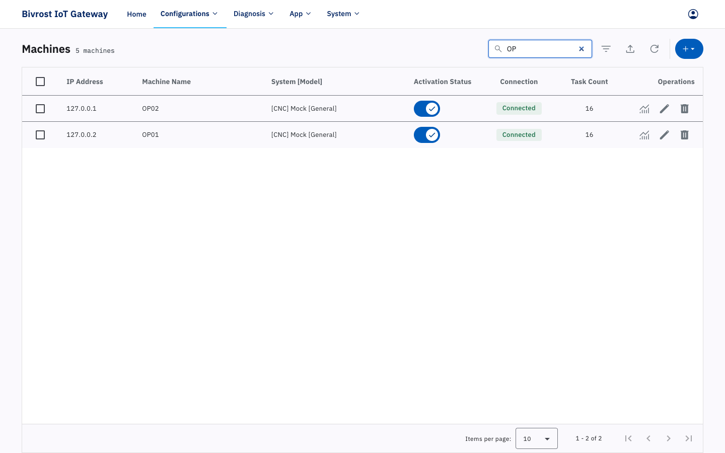
Type a keyword into the 🔍 Find Machine box and the matching machines appear below. The search covers IP address, machine name and system model. Clear the box to show all machines again.
Click ↻ Refresh to reload the whole machine list.
Click + Add Machine to add a machine — see 3.3.1. Adding a Machine.
3.3.1. Adding a Machine
Section titled “3.3.1. Adding a Machine”Click + Add Machine at the top right. The drop-down menu contains Create CNC, Create Laser Cutter, Create Robot and Create PLC.
The dialogs for the different machine types are similar. The main differences are:
- the tasks available on the Task tab differ by machine type;
- robot and PLC machines have no DNC tab;
- some machines have special settings (see the machine setup documentation, or contact support).
The example below adds a CNC machine:
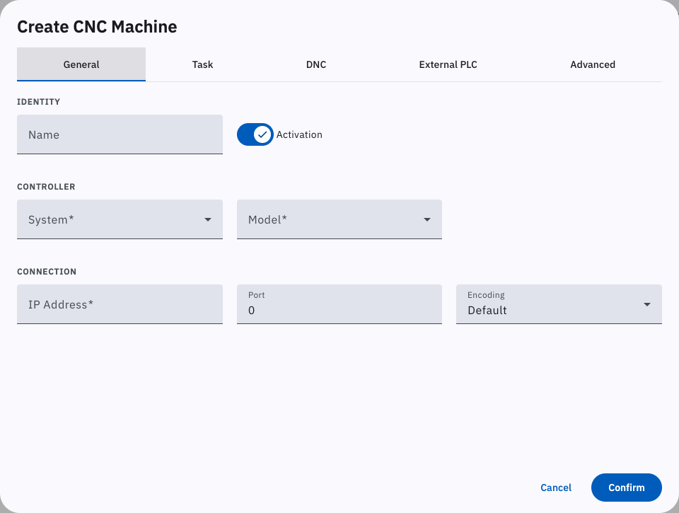
Click Create CNC. The “Create CNC Machine” dialog opens with the tabs “General”, “Task”, “DNC”, “External PLC” and “Advanced”. Fill in all of the tabs and click Confirm to add the machine. Anything you need to change afterwards can be edited in the “Edit CNC Machine” dialog (see 3.3.2. Editing a Machine).
3.3.1.1. General Settings
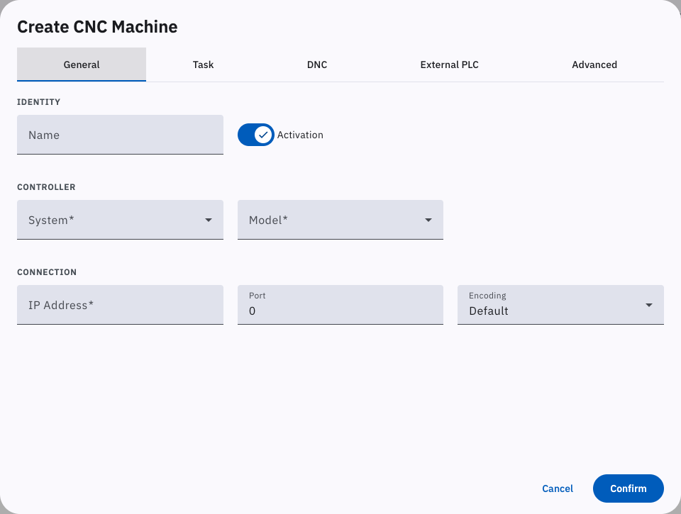
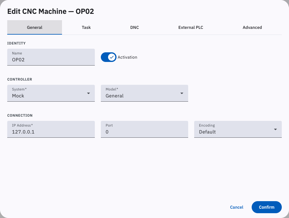
Section titled “3.3.1.1. General Settings”The “General” tab holds the machine’s connection settings: choose “System” and “Model”, enter the machine’s IP address and machine name, and select an encoding. If you choose Mock as the system, the IP address must be 127.0.0.X, where X is 1–255. Note that when “Activate” is selected in the dialog the machine is license-activated: it uses one collection license and collection is running. Clearing the checkbox withdraws the collection license used by that machine, pauses collection, and makes the withdrawn license available to another machine.
If the communication port on the machine is set to something other than the default, set “Port” to the matching value; otherwise leave it at 0 to use the default port. The encoding option is used when parsing text (alarm text, String values in PLC data, file names, the contents of received files, and so on); the wrong encoding produces garbled text. The default is normally correct.
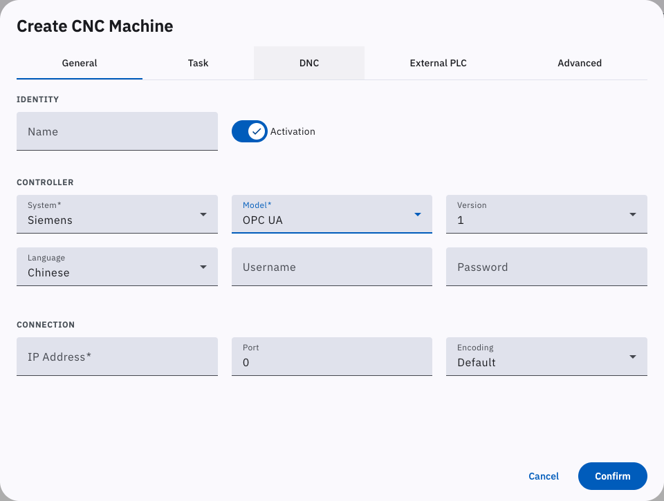
Some models and connection methods — such as Siemens machines that expose an OPC UA service — require the OPC username and password configured on the machine. The fields are hidden for models and connection methods that need no credentials.
3.3.1.2. Task Settings
Section titled “3.3.1.2. Task Settings”The “Task” tab configures the machine’s automatic collection tasks. Select an available interface to turn on automatic collection for the corresponding task. Interfaces not covered by your license are shown as “Unlicensed” and cannot be selected. The number of enabled tasks appears in the “Task Count” column of the Machines page.
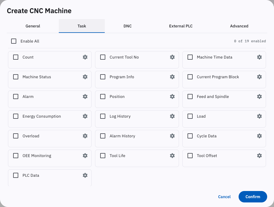
This tab turns the machine’s automatic collection tasks on and off. Task results can be published through the cloud platform, MODBUS, MQTT or a database. To receive task results you must enable and configure at least one of the cloud, MODBUS, MQTT or database transports in 3.6. Communication. Collection intervals and detailed task settings are configured in 3.5. Tasks. For the format in which task results are published over MODBUS, MQTT and databases, see 6. MODBUS Communication, 7. MQTT Communication and 8. Database Communication. Collection through the HTTP interfaces does not require any machine task to be enabled.
The ⚙ button to the right of a task opens its advanced settings — Precondition, Target Channels, Target Tools, Custom Functions, Special Settings and so on.
3.3.1.2.1. Precondition
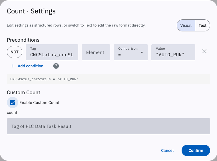
Section titled “3.3.1.2.1. Precondition”When a precondition is set, the gateway evaluates it before each run of the task and only performs the collection if the condition is met. Left blank, the task has no precondition and always runs. For the precondition syntax, see 11.2.2. Precondition.
For example:
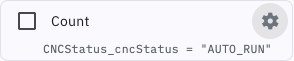
CNCStatus_cncStatus = "AUTO_RUN" and Load_spindleLoad[0] > 50Tasks that have a precondition are marked with a blue branch icon to the right of the task name.
3.3.1.2.2. Target Channels
Section titled “3.3.1.2.2. Target Channels”Some machines expose data for several channels — for example channel 1 for the main spindle and channel 2 for the sub-spindle. The default target channel is 0, which collects data from the main channel only. To collect data from several channels, list them under target channels. The tasks that support this setting include Current Tool No, Machine Status, Program Info, Current Program Block, Position, Feed and Spindle, Load, Overload and Cutter comp.
For example: 0;1-3
3.3.1.2.3. Target Tools
Section titled “3.3.1.2.3. Target Tools”The Tool Life and Cutter comp tasks require target tools to be entered in the dialog behind the ⚙ button next to the task. How tools are specified depends on the machine’s control system; by default no tools are specified. Follow the example in the hint text, or see 5.5.1.14. readOffsetData (Read Offset Data) and 5.5.1.23. readToolLife (Read Tool Life).
On a Siemens control, for instance, a tool is defined by a tool number (Tool) and an offset number (Offset):
1.2;3-5.1;7-9.1-31.2means tool 1, offset 2;3-5.1means tool 3 offset 1, tool 4 offset 1 and tool 5 offset 1;7-9.1-3means tools 7, 8 and 9, offsets 1, 2 and 3 on each of them.
3.3.1.2.4. Custom Functions
Section titled “3.3.1.2.4. Custom Functions”The Count, Machine Status and Alarm tasks support custom functions, which substitute the result of a PLC task for the data returned by the native interface. Custom functions are mainly used on controls where a customised module replaces the native one, or where the control does not support the required communication and the manufacturer supplies an address list so the data can be read from PLC addresses instead.

3.3.1.2.5. Special Settings
Section titled “3.3.1.2.5. Special Settings”The Machine Status task supports adjusted status settings: you can enable manual-status adjustment and status conversion, both off by default. These are the same settings as the ones with the same names in 3.5.8. Machine Status Monitoring Settings; those are global, and enabling them here overrides the global settings for this machine.
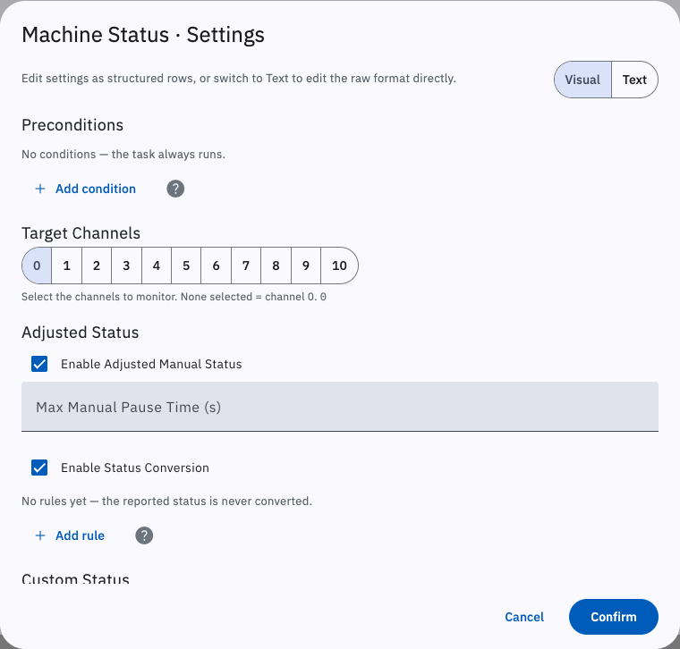
With Enable Adjusted Manual Status or Enable Status Conversion turned on, the status is adjusted according to the corresponding rules and published as adjustedStatus (4.2.4. CNCStatus: Machine Status). Calculations that involve machine status — OEE, cumulative status time and so on — use the adjusted status in preference to the raw one. With both options off, adjustedStatus is identical to the real-time status reported by the machine.
The rules for manual-status adjustment are:
- the machine is currently in the Manual state;
- the time since the machine went from a non-Manual state to Manual exceeds the configured Max Manual Pause Time;
- the machine’s position data has stayed unchanged for longer than the configured Max Manual Pause Time.
Normally adjustedStatus matches the machine’s real-time status; when all of the conditions above are met at once, adjustedStatus is no longer Manual but is adjusted to Wait.
With status conversion enabled, adjustedStatus is set according to the commands you enter, for example:
CNCStatus_cncStatus = "MANUAL_MDI_RUN" | AUTO_RUNCNCStatus_cncStatus = "MANUAL_MDI_RUN" is the precondition (see 11.2.2. Precondition): if the cncStatus value (the running status, of type String) returned by this machine’s Machine Status task is “MANUAL_MDI_RUN”, then adjustedStatus is set to AUTO_RUN. Separate multiple conversion commands with “;”.
When both options are enabled, manual-status adjustment runs first and status conversion second.
The PLC Data task requires the commands for the target PLC data to be entered in the dialog behind the ⚙ button next to the task — see 11.2.1. PLC Data Task.
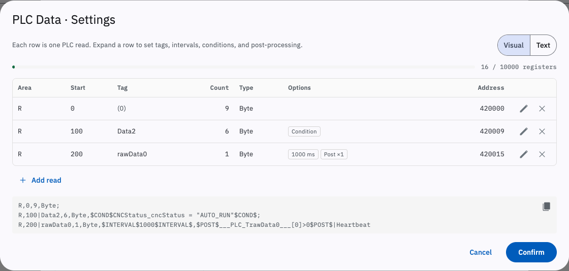
If MODBUS communication is enabled (3.6.2. MODBUS Settings), the reserved MODBUS address space limits a single machine’s PLC data tasks (including external PLC data) to 10000 address registers after conversion — see 6.1. Machine-related Data.
3.3.1.2.6. Alarm Mapping
Section titled “3.3.1.2.6. Alarm Mapping”The Alarm task supports alarm mapping, which replaces the alarm numbers reported by the machine with your own alarm text. It suits machines that report only an alarm number and no alarm text, or installations where alarm descriptions need to be standardised.
In the dialog behind the ⚙ button next to the Alarm task, select “Enable Alarm Mapping” and then pick an uploaded mapping file from the “Alarm Mapping File Name” drop-down.
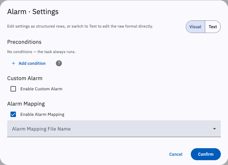
Mapping files are uploaded and managed in 3.5.7.1. Alarm Mapping Files; a file must be uploaded there before it can be selected here. After enabling it, click Confirm to save, then go to Home and click Restart Service to apply the change.
3.3.1.2.7. Additional Notes
Section titled “3.3.1.2.7. Additional Notes”Machine OEE data covers Off Time, Wait Time, Emergency Time, Autorun Time, Manual Time and machine Availability — see 11.1.1. Machine OEE Data. OEE data depends on local caching, so the “Local Caching” switch under Options in 3.12. Settings must be turned on.
Write Offset Data and DNC are not available as machine tasks; they must be called through the HTTP interfaces or the MQTT RPC interfaces — see 5. HTTP Communication and 7.2. RPC Interface.
Cumulative Status Time is the total time spent in each status since the gateway started collecting from the machine, in seconds. The value is stored on the gateway, bound to the machine ID (MachineID), and is never reset.
Cycle Data gives the duration of the last cycle; the gateway derives it from Machine Status, Count and Program Info.
3.3.1.3. DNC Settings
Section titled “3.3.1.3. DNC Settings”The “DNC” tab sets the file transfer method and target location.
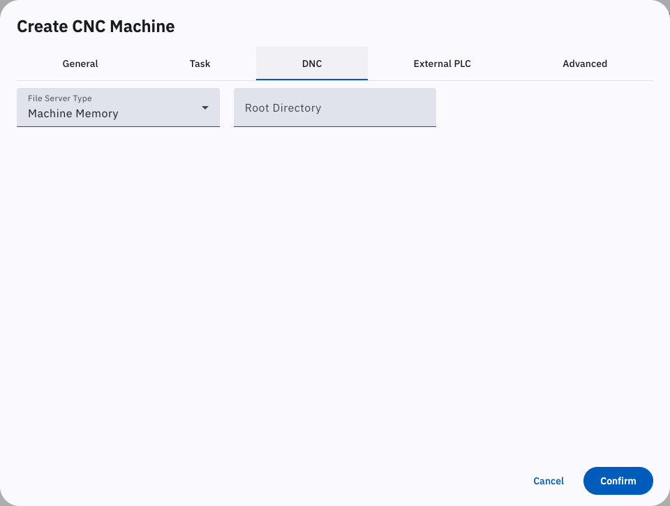
The “File Server Type” options are:
- Machine Memory (default), the machine’s built-in storage, including a CF card plugged into the machine (supported on some machines; the root directory must point at the CF card path);
- Shared Folder and Shared Folder (Win XP), which transfer files through a shared folder;
- FTP Server, which transfers files over FTP;
- Wireless Disk, an external storage device attached to the machine that connects to the gateway over WiFi and to the machine over USB or RS232;
- Gateway File Server, a file server hosted on the gateway itself that the machine can reach over FTP or a shared folder — see 3.6.5. Gateway File Server Settings.
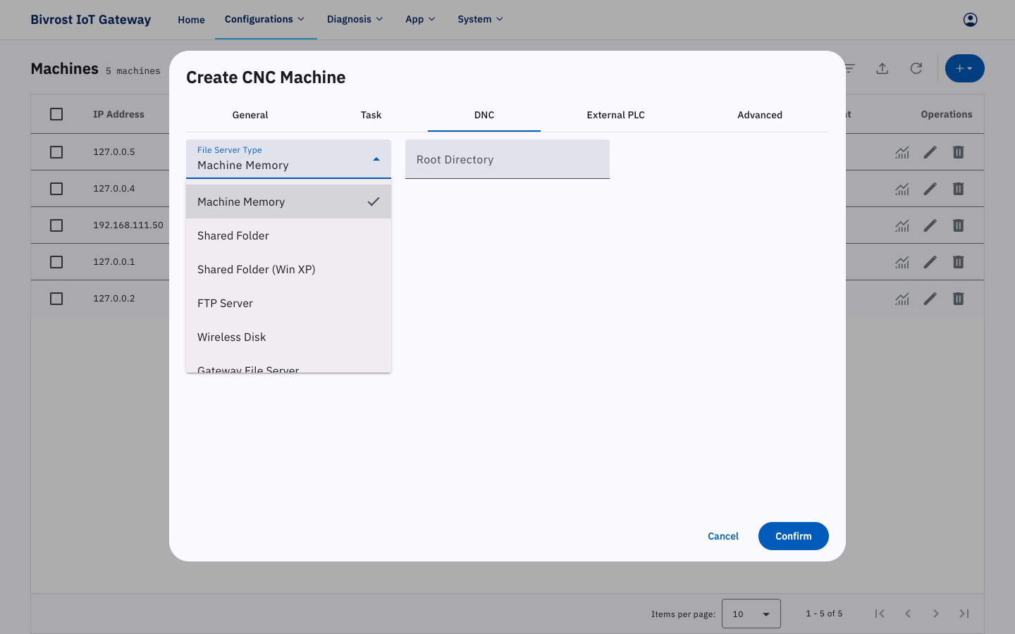
If the machine’s own storage is too small, or the machine does not support transferring programs directly to its internal storage, use the “Gateway File Server” instead. You can also attach file server hardware to the machine and transfer programs through “Shared Folder”, “FTP Server” or “Wireless Disk”.
If the root directory is left blank, the machine’s default path is used. The default path differs by machine model — see 5.6. File Management Interfaces.
3.3.1.4. External PLC Settings
Section titled “3.3.1.4. External PLC Settings”The “External PLC” tab lets you add commands that collect data from an external PLC attached to equipment around the machine — see 11.2.5. External PLC Data Task. Once a valid external PLC data task has been added, collection starts automatically after a service restart. The collection interval for external PLC data tasks, and the way their results are retrieved, are the same as for PLC data tasks.
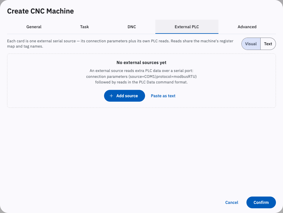
For example:
source=COM1|protocol=modbusRTU;4x,0,1,Int16;4x,10,2,Int323.3.1.5. Advanced Settings
Section titled “3.3.1.5. Advanced Settings”The “Advanced” tab lets you customise the machine ID (MachineID), the slave ID (SlaveID), Network Error as Offline, Parallel Task Processing, and custom attributes.
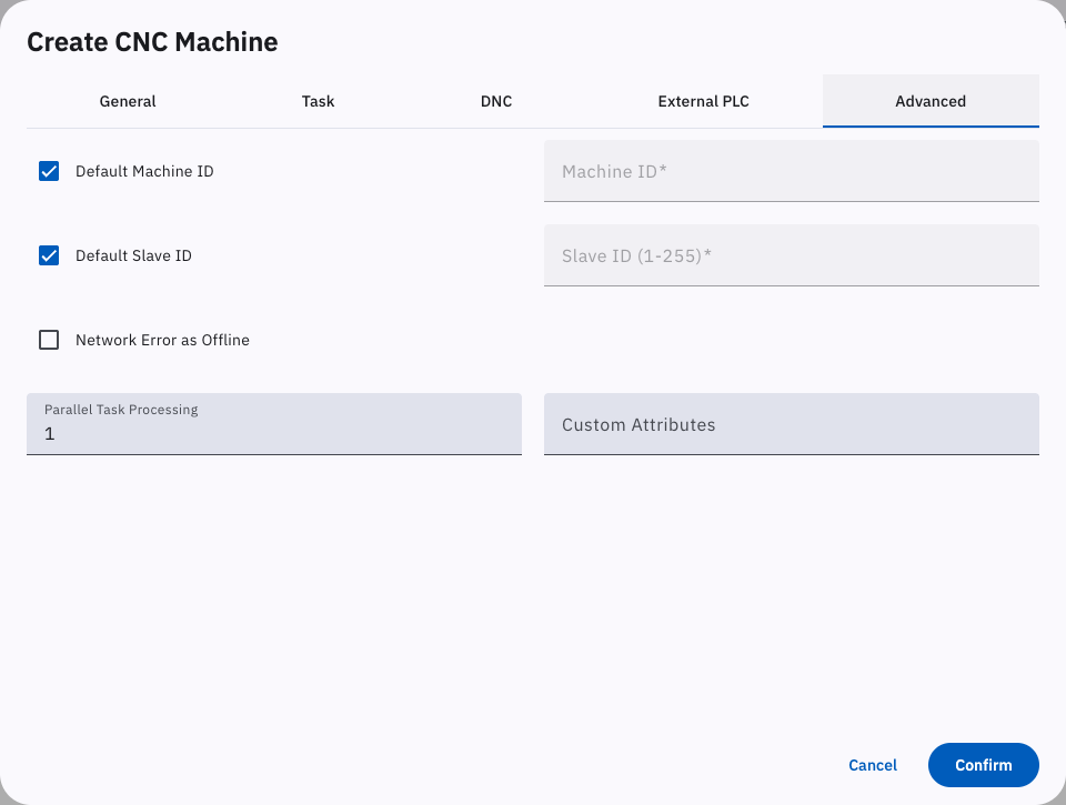
Machine ID identifies the machine’s data on every transport except Modbus. The default machine ID is formed by joining the third and fourth octets of the machine’s IP address and stripping the leading zeros. If the third octet is not 0, the fourth octet is padded to three digits. For example, 192.168.0.1 gives a default machine ID of 1, and 192.168.1.12 gives 1012.
Slave ID identifies the machine’s data on Modbus. The default slave ID is the fourth octet of the machine’s IP address; 192.168.1.12 gives a default slave ID of 12.
Network Error as Offline is off by default. When it is on and the machine fails to connect for network reasons on the first attempt (previously reported as “Network Error”), the gateway treats the machine as offline instead of reporting a connection error. This suits machines that are powered down or lose network connectivity from time to time, where all such unreachable states should be treated uniformly as offline.
Parallel Task Processing is the number of task managers — that is, threads — allocated to the machine. The default is 1. Raising it consumes more system resources, so only raise it when the machine has a large number of tasks with very short intervals and the default setting cannot keep collection up to date. Some control systems do not support multi-threaded connections and must be left at 1. Note that the sum of the Parallel Task Processing values of all activated machines should be less than the maximum number of task managers (see 3.5.9. Task Manager Settings).
Custom Attributes add user-defined attribute tags to the task data returned by the gateway. The format is:
{"attribute":value,…}Example:
{"Custom ID":1, "Custom String": "abc123 string"}In the task data, custom attributes are added after the <entityID> attribute (MachineID, in the case of a machine).
3.3.1.6. Connection Status
Section titled “3.3.1.6. Connection Status”Once everything in the create machine dialog is set, click Confirm to save. The new machine appears on the Machines page. Note that its “Connection” icon is a yellow circle at this point, meaning the machine is not loaded; go to Home and click Restart Service to load the newly configured machine.

After the Restart Service, the Connection icon turns into a green check, meaning communication is working. Any other icon means the configuration is wrong or there is a fault in the machine, the gateway or the network — hover over the icon for an explanation, or refer to the table of common connection icons in 3.3. Machines.

3.3.2. Editing a Machine
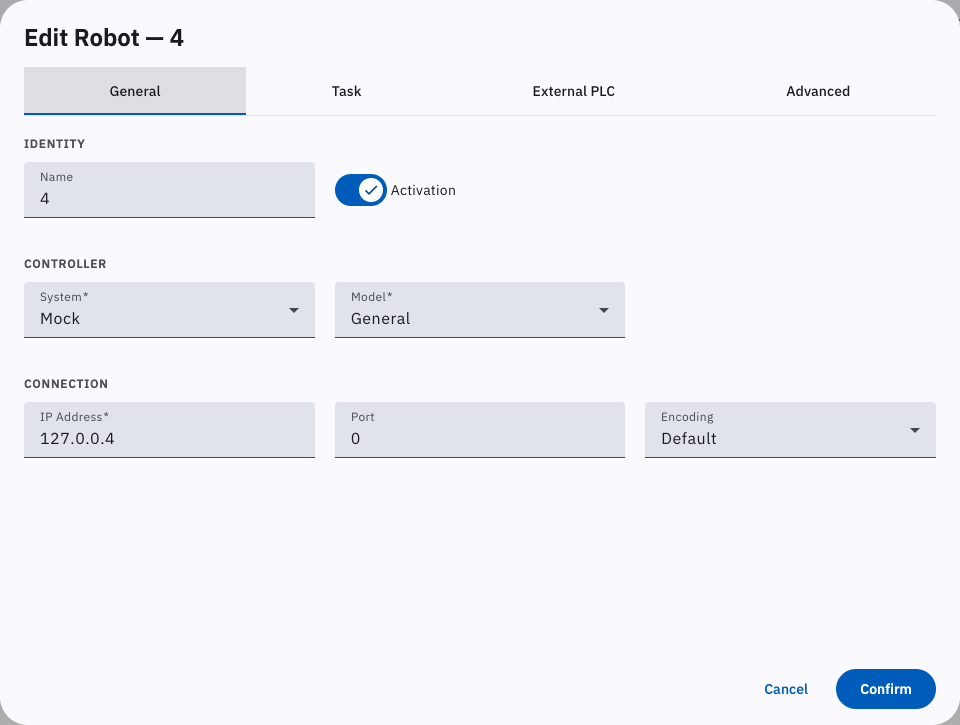
Section titled “3.3.2. Editing a Machine”Click the edit button ✏️ in the “Operations” column at the right of a row in the machine list. The “Edit CNC Machine” / “Edit Laser Cutter” / “Edit Robot” / “Edit PLC Machine” dialog opens; it is similar to the corresponding “Create CNC Machine” / “Create Laser Cutter” / “Create Robot” / “Create PLC Machine” dialog. For a description of each tab, see 3.3.1. Adding a Machine. The machine type — CNC, laser cutter, robot or PLC — cannot be changed in the edit dialog.
3.3.3. Deleting a Machine
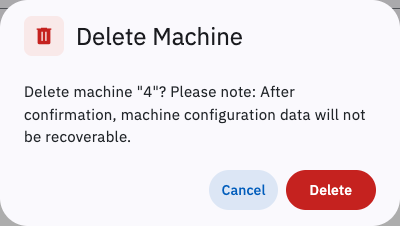
Section titled “3.3.3. Deleting a Machine”Click the delete button 🗑️ in the “Operations” column at the right of a row in the machine list. The “Delete Machine” dialog appears; click Confirm to delete the machine permanently.
3.3.4. Batch Activation
Section titled “3.3.4. Batch Activation”Select several machines using the checkboxes at the far left of the list, or the select-all button at the top left of the list.
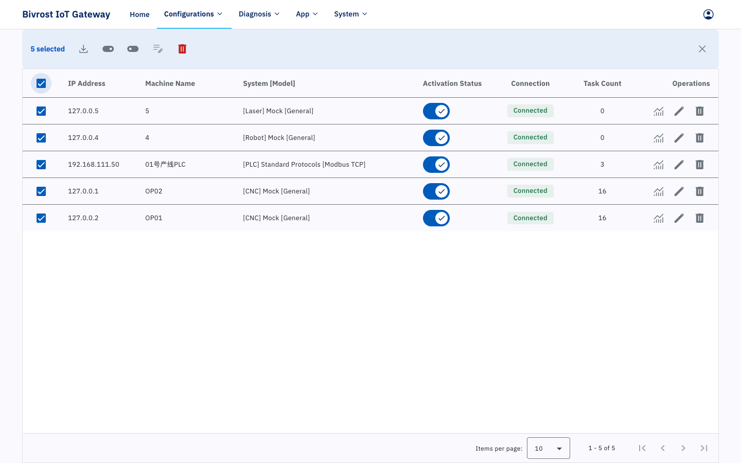
The batch buttons — Batch Activation, Batch Edit and Batch Delete — then appear at the top right.
Click Batch Activation, choose whether to activate, and click Confirm to set the selected machines to activated or unactivated.
3.3.5. Batch Edit
Section titled “3.3.5. Batch Edit”Select several machines using the checkboxes at the far left of the list, or the select-all button at the top left of the list. Note that they must all have the same system and model.
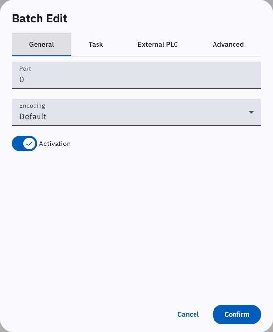
Click Batch Edit at the top right, set the shared options in the Batch Edit dialog, and click Confirm to save.
3.3.6. Batch Delete
Section titled “3.3.6. Batch Delete”Select several machines using the checkboxes at the far left of the list, or the select-all button at the top left of the list.
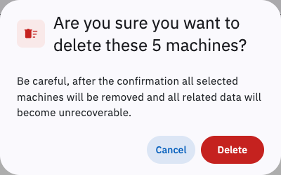
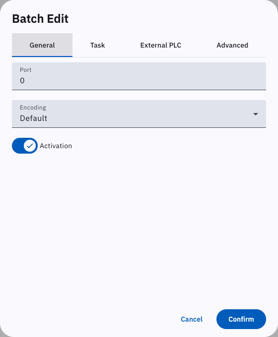
Click Batch Delete at the top right and click Confirm in the confirmation dialog to delete the selected machines.