
3.8. API Test
This page exposes a selection of read and write interfaces so you can verify them before going live. Full descriptions of every interface on this page can be found under 5.5.1. Direct Read/Write.
Before running an API test, if you have changed any settings on Machines, Groups, Tasks or Communication, click Restart Service on Home first.
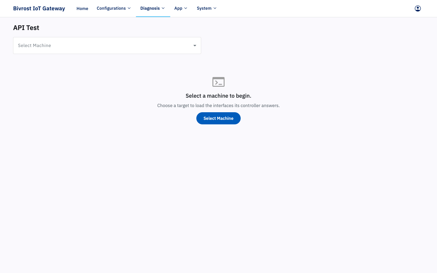
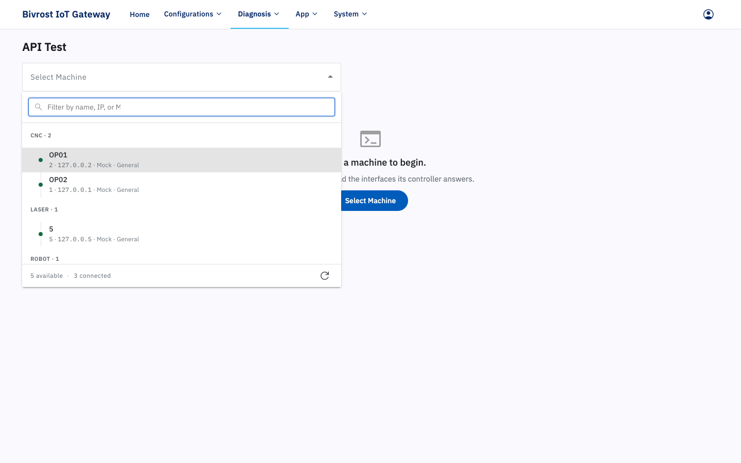
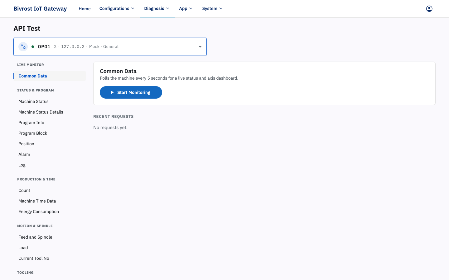
In the Select Machine box at the top, pick a machine that is activated on the Machines page, then pick the HTTP interface you want to test from the interface list (Common Data by default). Click Monitoring/Send to retrieve data from that interface on that machine.
3.8.1. Common Data Interface
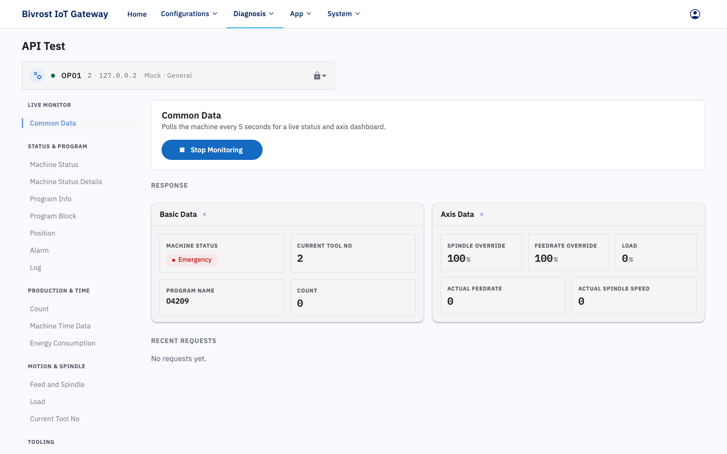
Section titled “3.8.1. Common Data Interface”Monitoring common data polls a set of frequently used interfaces at a regular interval (roughly every 5 seconds) — Machine Status, Program Info, Current Tool No, Count, Alarm and so on — and refreshes the data as shown below. Click Stop Monitoring to leave monitoring.
3.8.2. Read Data Interfaces
Section titled “3.8.2. Read Data Interfaces”Apart from the Common Data interface and the Write PLC Data and Write Offset Data interfaces, every interface is a read interface. Send a request on a read interface — the Count interface, for example — and you get the result shown below. The Count interface returns the machine’s part count. The line below that begins with /api/cnc/ is the HTTP interface address. The result is inside {}, where “count” is the name and 2806 is the value for that name. For a detailed description of each interface, see the corresponding entry under 5.5.1. Direct Read/Write.
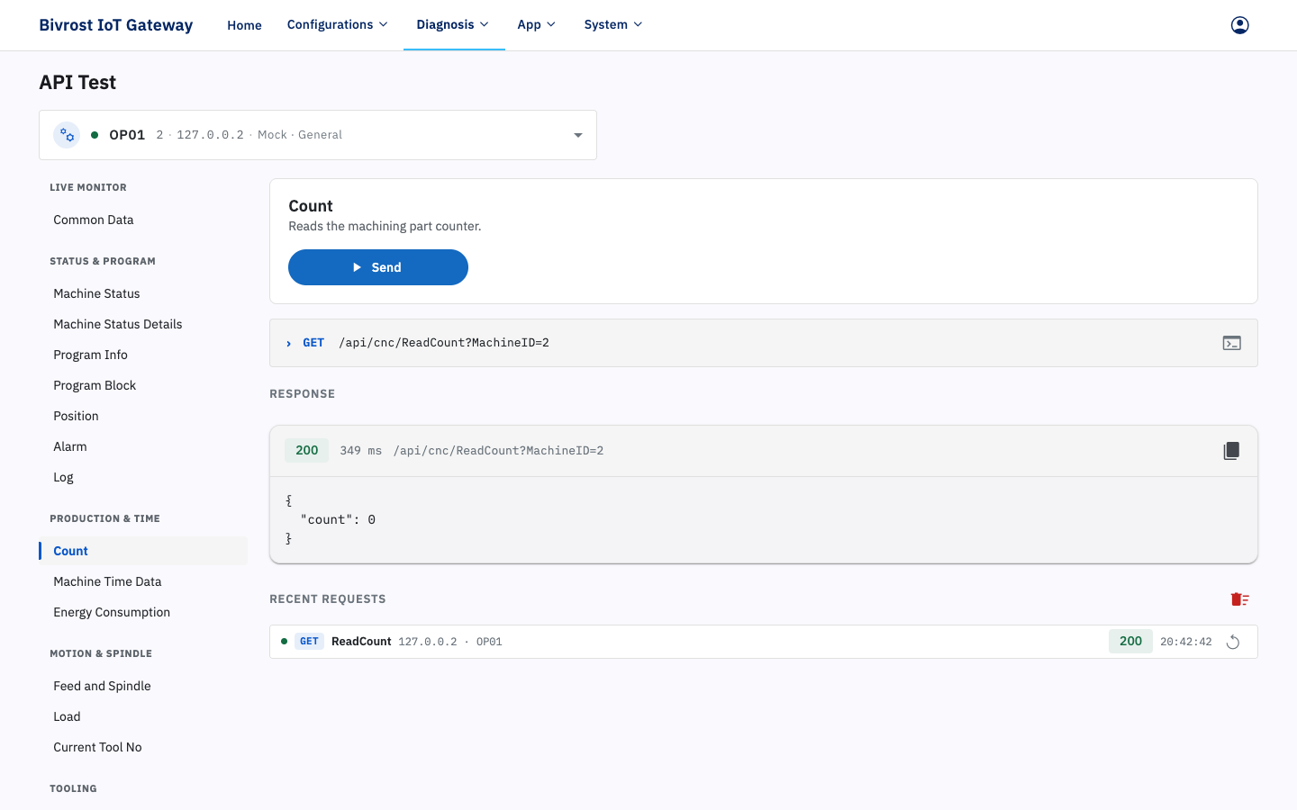
/api/cnc/ReadCount?MachineID=2118
{  "count": 2806}
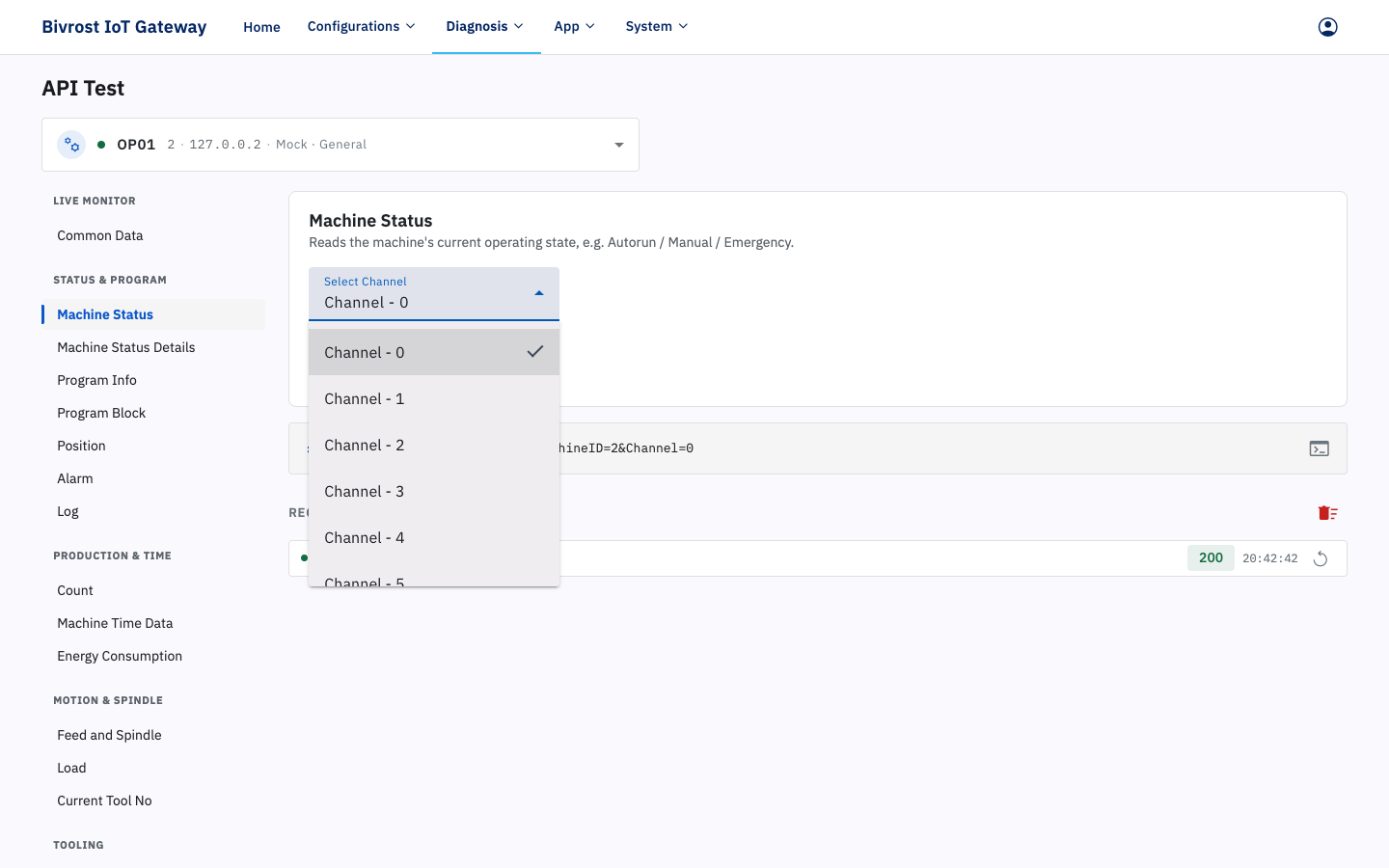
Some interfaces support multi-channel machines and can return data for a specific channel number. The default is channel 0, the main channel. On a single-channel machine, leave it at channel 0. The example below reads the status of a specific channel through the Machine Status interface.
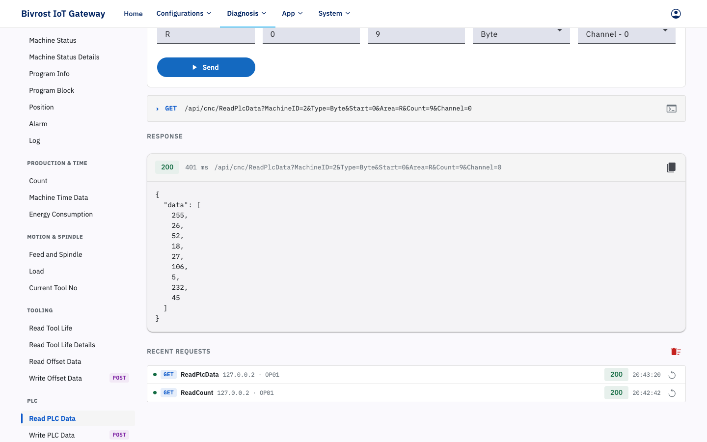
The Read PLC Data interface needs additional inputs such as Area, Start Address, Data Count and Data Type. See 11.2.1. PLC Data Task and 5.5.1.20. readPlcData — Read PLC Data.
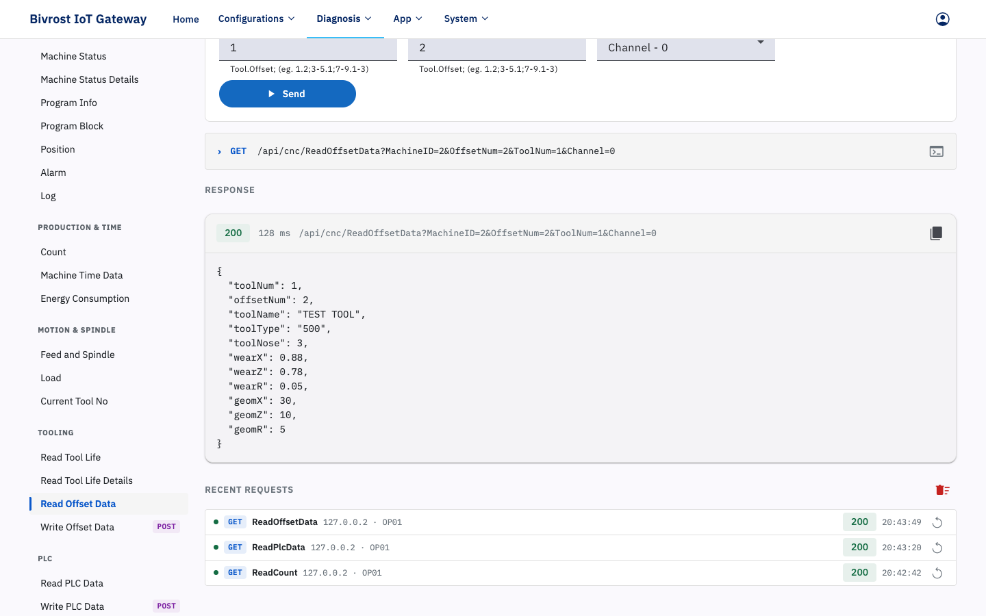
The Read Offset Data interface needs inputs such as the Offset Number; see 5.5.1.14. readOffsetData — Read Offset Data.
The Read Tool Life and Read Tool Life Details interfaces need different inputs depending on the machine’s controller model. In this example the controller is a Fanuc, so the tool’s Group Number and Tool Index within that group are required; see 5.5.1.23. readToolLife — Read Tool Life.
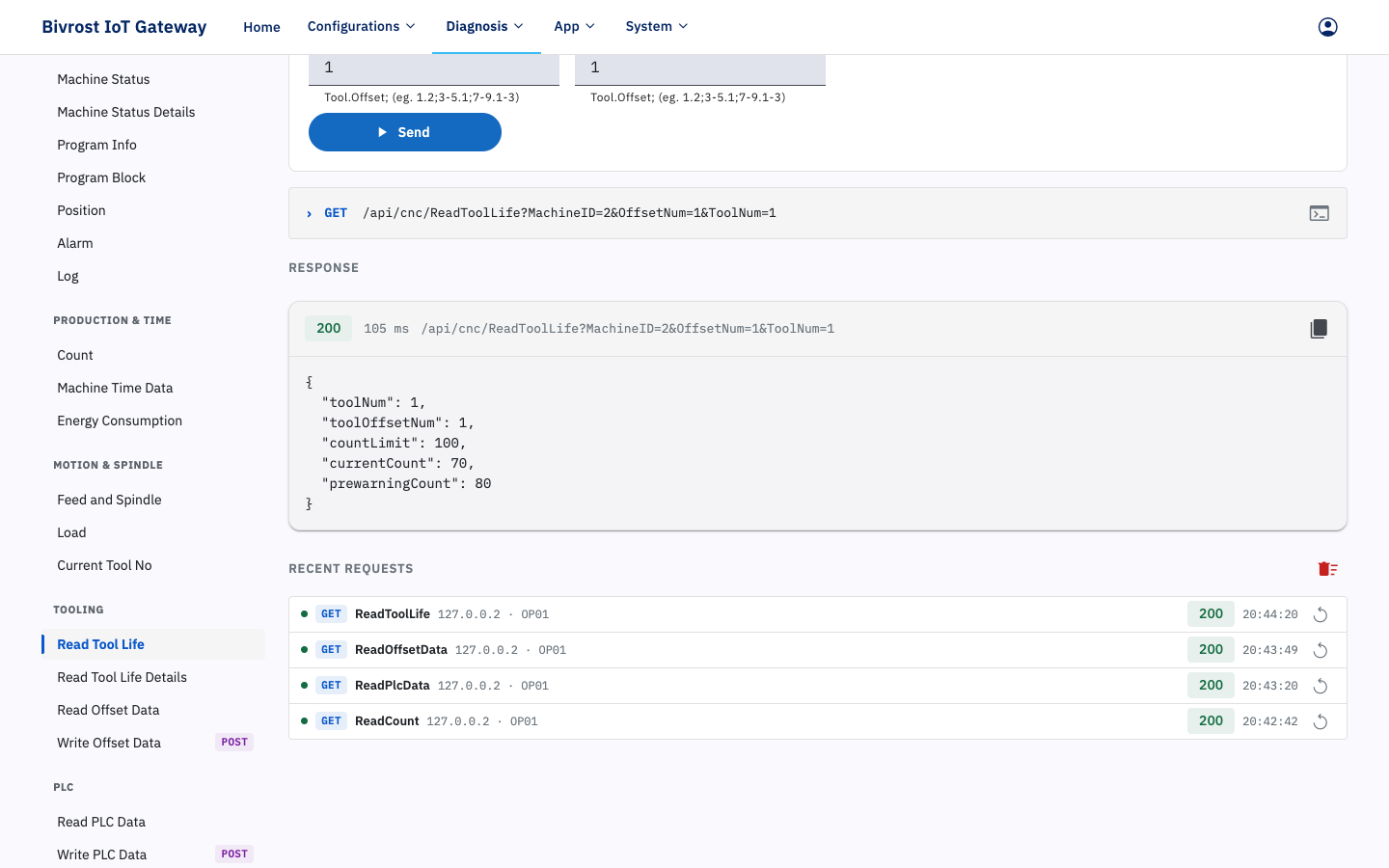
3.8.3. Write Data Interfaces
Section titled “3.8.3. Write Data Interfaces”The write interfaces are Write PLC Data and Write Offset Data. Like the Read PLC Data and Read Offset Data interfaces, they need inputs such as Area, Start Address, Data Type and Offset Number, and in addition you must supply the data to be written in the request body. See 5.5.1.21. writePlcData — Write PLC Data and 5.5.1.16. writeOffsetData — Write Offset Data. Click Beautify to reformat the request body into standard JSON.
Example request body for writing PLC data:
{ "data": [ 1, 2, 3 ]}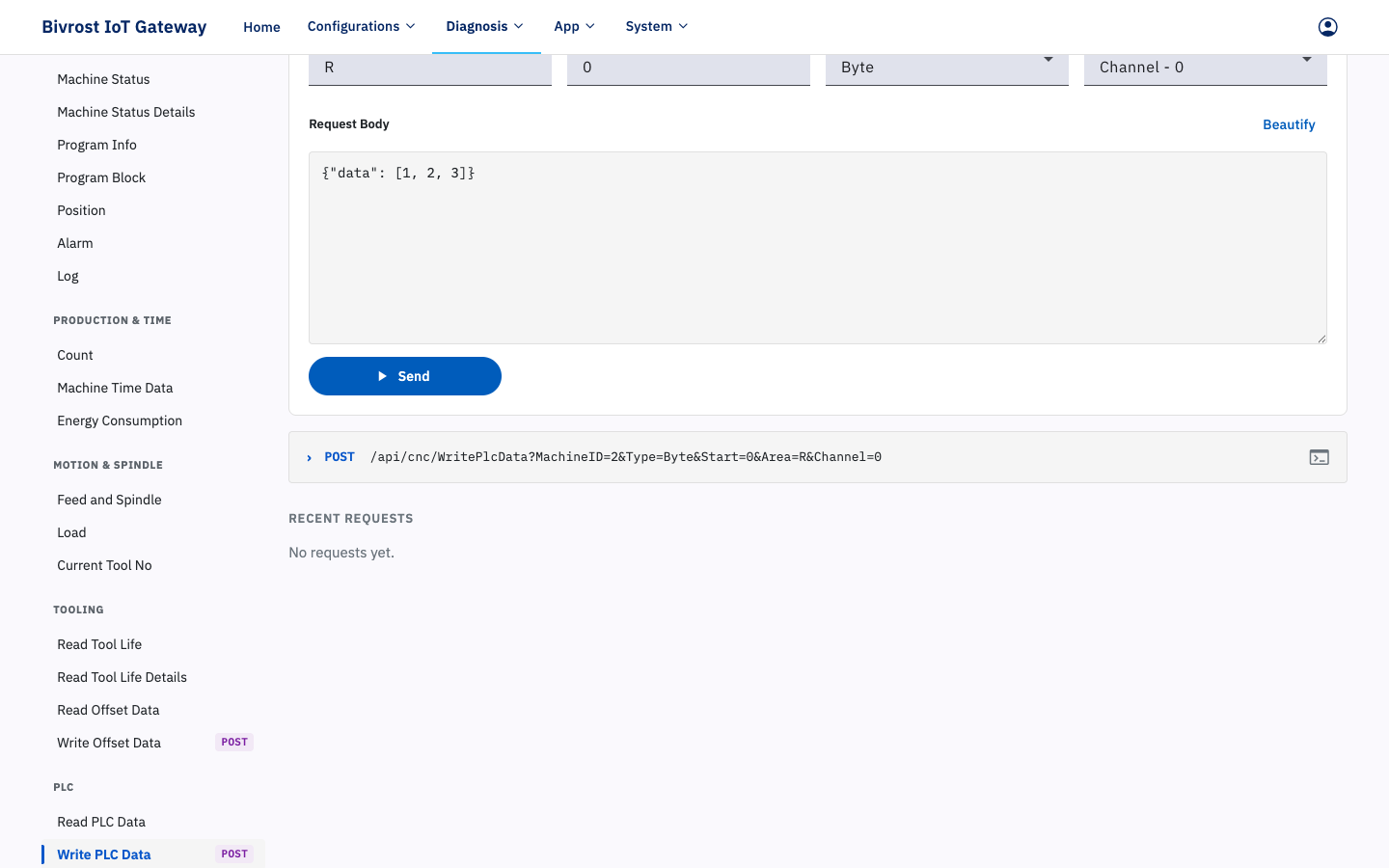
Example request body for writing offset data:
{ "lengthWear": 0.0011, "radiusWear": 0.13, "lengthGeom": 0.1, "radiusGeom": 0.012}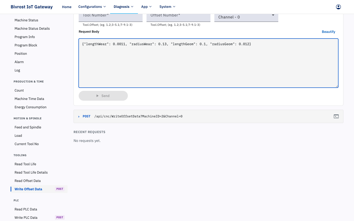
A successful write returns an error code (errorCode, where 0 means success) and an error message (errorMsg); see 5.2. Error Handling.
{ "errorCode": 0, "errorMsg": "Success"}3.8.4. Troubleshooting Test Failures
Section titled “3.8.4. Troubleshooting Test Failures”A failed API test returns Failed to Call API, as shown below. The response gives an Error Code, a Description, Details and a suggested Remedy.
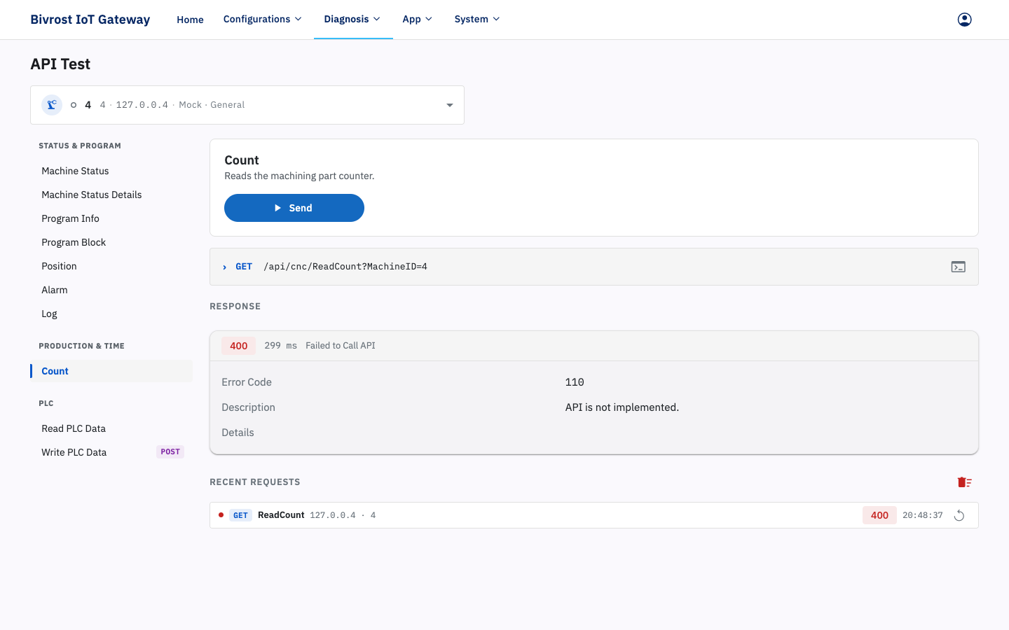
If an API test fails, check the following:
- The settings on the Machines page;
- Whether you clicked Restart Service on Home after changing anything on the Machines or Tasks page;
- Whether the network settings on the machine are correct — on some machines the settings only take effect after the power is switched off for three seconds and back on;
- Whether the hardware — network cable connections, switches and so on — is properly connected;
- Whether the machine’s IP address is already in use. When office PCs or other devices share the same LAN, the machine’s IP may be taken, which stops the machine and the gateway from communicating. Try giving the machine an IP address that is not in use. Note: an IP address that does not answer a ping is not necessarily free — some devices disable ping replies for security reasons.
- Another form of address conflict is a subnet conflict. This is common when the data-acquisition network and another internal network share a switch and both use the same subnet. When this happens, move either the conflicting internal devices or the data-acquisition network to a subnet that is not in use.