
3.6. Communication
Communication covers Cloud Settings, MODBUS Settings, MQTT Settings, Database Settings, Gateway File Server Settings, HTTP Settings, Hub Settings, MCP Settings and so on. You can turn on one or more of these communication methods as required.
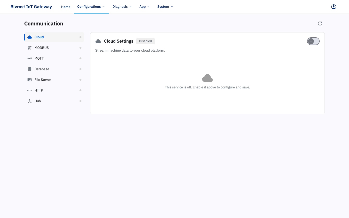
The left side of the Communication page lists the available communication methods (and shows whether each one is enabled); the right side holds the settings for the selected method. Turn on the Enable switch in those settings to show all of the fields. Except for MCP Settings, after you click Save you must go back to Home and click Restart Service to apply the changes.
3.6.1. Cloud Settings
Section titled “3.6.1. Cloud Settings”Click the Enable switch to turn on cloud platform communication.
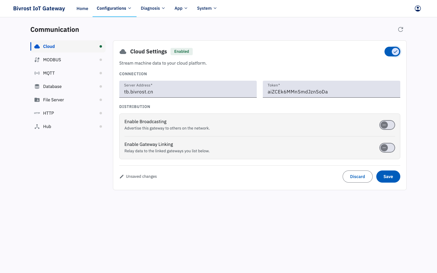
After completing Cloud Settings, saving, restarting the service and confirming that the gateway is connected to the cloud platform, replace the gateway address in the HTTP request URL with the cloud platform server address and add an AccessToken request header whose value is the gateway token entered in Token on this page. See 5.1.1. Forwarding Requests Through the Cloud Platform or Hub for instructions and an example.
Once cloud communication is enabled, the server settings are complete and the automatic collection tasks of the target machines and groups are switched on (see 3.3.1.2. Task Settings and 3.4.1.2. Group Task Settings), task data is uploaded in real time to the designated standard cloud platform over a standard protocol, where it can be stored, analysed and shown on dashboards. Bivrost runs a standard cloud platform server at tb.bivrost.cn; contact support to arrange a trial.
- Enter the cloud platform address in Broker Address.
- Enter the token the cloud platform has assigned to the gateway in Token.
- With Enable Broadcasting on, the gateway broadcasts data through the cloud platform to the other gateways on that platform.
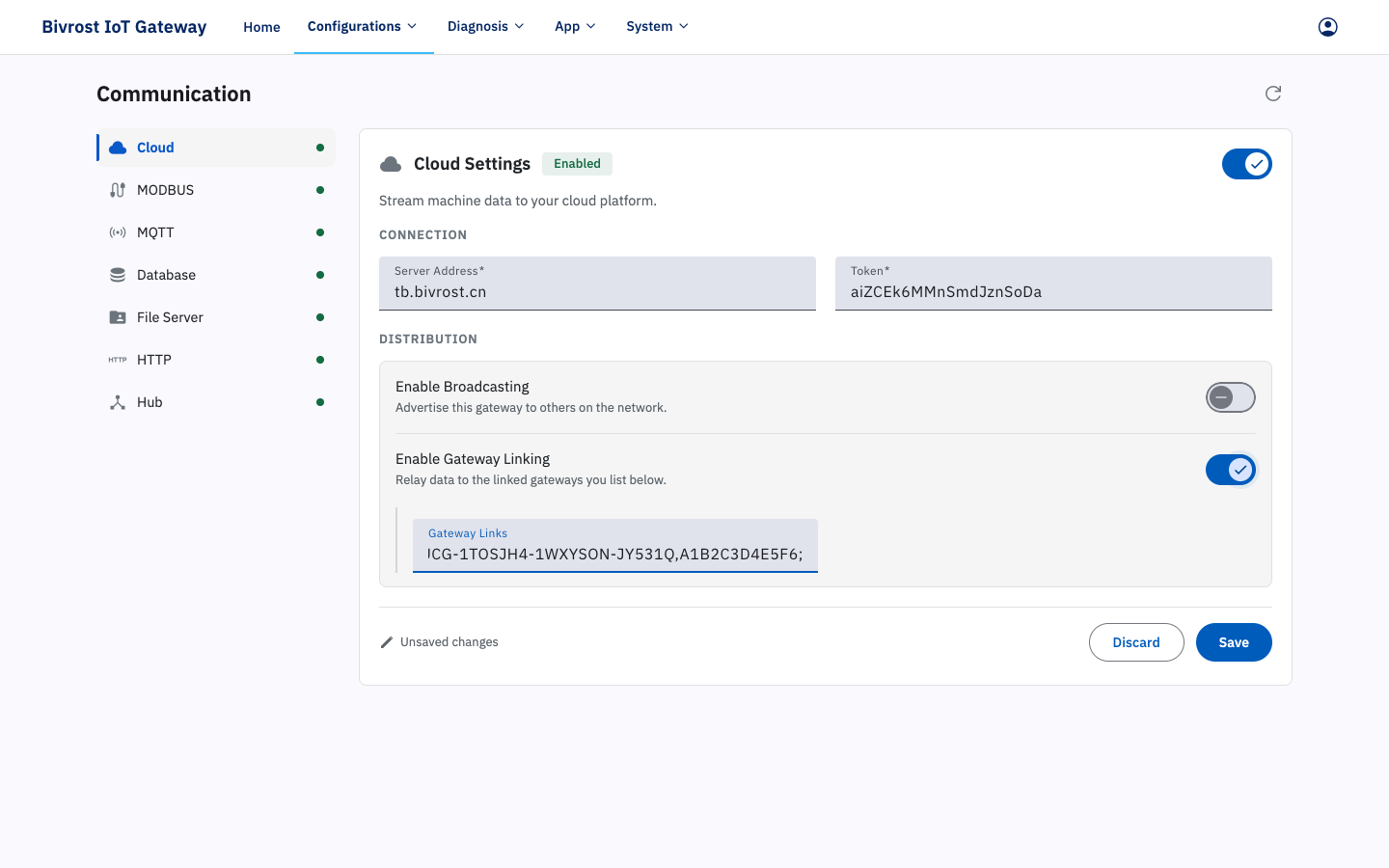
- With Enable Gateway Linking on, the gateway receives data broadcast through the cloud platform by the other gateways on that platform. Add the UID and token of each gateway you want to link to under Gateway Links, in the following format:
UID,token;Separate multiple linked gateways with ;.
3.6.2. MODBUS Settings
Section titled “3.6.2. MODBUS Settings”Click the Enable switch to turn on MODBUS communication.
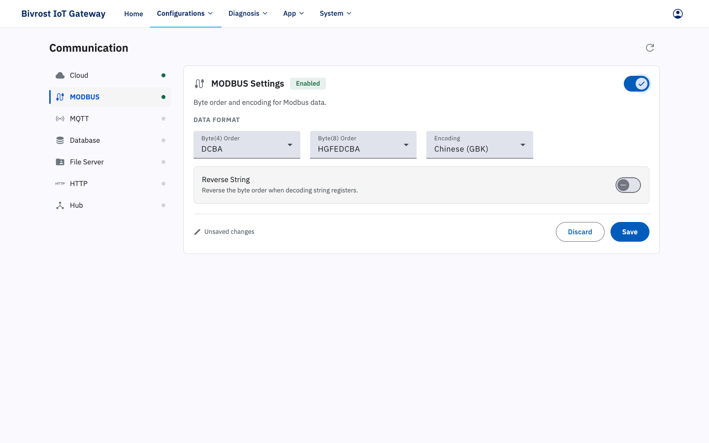
Once MODBUS communication is enabled and the automatic collection tasks of the target machines and groups are switched on (see 3.3.1.2. Task Settings and 3.4.1.2. Group Task Settings), the gateway uses the MODBUS protocol to store the task data in the corresponding address registers — see 3, MODBUS Communication,.
- Byte(4) Order selects the decoding format used in MODBUS communication for 32-bit data (long integers such as Int32, single-precision Float and any other type that occupies two register addresses). The default is “DCBA”.
- Byte(8) Order selects the decoding format used in MODBUS communication for 64-bit data (double-precision Double and any other type that occupies four register addresses). The default is “HGFEDCBA”.
- Encoding selects the string encoding used by the MODBUS protocol. The default is “Chinese (GBK)”.
- With Reverse String on, the character order of strings is reversed.
3.6.3. MQTT Settings
Section titled “3.6.3. MQTT Settings”Turn on the Enable switch to start MQTT communication.
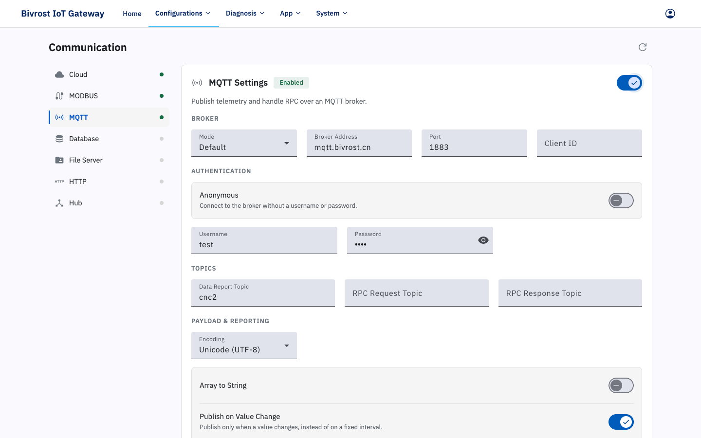
Once MQTT communication is enabled and the automatic collection tasks of the target machines and groups are switched on (see 3.3.1.2. Task Settings and 3.4.1.2. Group Task Settings), the gateway publishes the task data as JSON messages to the designated MQTT broker; see 7. MQTT Communication.
Select a Mode, then enter the broker address and port. The screenshot shows a standard MQTT mode, where you can set the Client ID, anonymous access or credentials, and data and RPC topics. Selecting GeWu (China Unicom Gewu Cloud) instead shows gateway and subdevice product settings. The gateway generates its Client ID and credentials, and the data topic is fixed by the platform.
- In standard modes, Data Report Topic is the topic used for automatic collection results. The default is “r”. GeWu mode uses the platform’s subdevice property topic; see 7.1. Data Upload Message Format.
- In standard modes, RPC Request Topic and RPC Response Topic configure the RPC interface. Both are blank by default, which disables it. Once set, the gateway subscribes to the request topic and publishes results to the response topic; see 7.2. RPC Interface.
- With Publish on Value Change on, the automatic collection tasks enabled in the machine task settings and group task settings only upload a result when the collected value has changed.
Connecting to Gewu Cloud
Section titled “Connecting to Gewu Cloud”- Create the thing model, gateway product, machine product, and group product on Gewu Cloud, then create the gateway device and obtain its device secret. The gateway uses per-device credentials. Machine and group subdevices use weak validation: they need neither preregistration nor individual secrets, but both subdevice products must allow dynamic registration.
- Enable the machines and groups to be reported. Their
machineID/groupIDbecomes each subdevice’sdeviceKeyand must contain 4–32 ASCII letters, digits, or underscores. Invalid subdevices are skipped. - Select GeWu, enter the broker address, port, and the fields below, save, then restart the service. The gateway generates its MQTT Client ID, username, and signed password, connects, and adds active machines and groups to its topology before it starts publishing their data.
| UI field | Value |
|---|---|
| Gateway Product Key | Product Key of the gateway product on the platform. |
| Gateway Device Key | Device Key of the gateway device; 4–32 ASCII letters, digits, or underscores. |
| Gateway Device ID | 10–32 ASCII letters, digits, or hyphens. |
| Gateway Device Secret | Device Secret generated for the gateway device. |
| Gateway Sign Method | HMAC-SHA256 (0) or HMAC-SM3 (1). |
| Gateway Operator | 0 for no cellular network; 1, 2, 3, or 4 for China Unicom, Mobile, Telecom, or Broadnet. |
| Machine Product Key | Product Key of the machine product. |
| Group Product Key | Product Key of the group product. |
All three Product Keys are required and cannot contain /, +, or #. If a topology addition fails, the gateway does not begin publishing subdevice data; check dynamic registration on the platform and the service log.
3.6.4. Database Settings
Section titled “3.6.4. Database Settings”Turn on the Enable switch to start database communication.
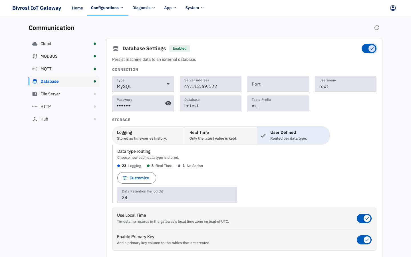
Once database communication is enabled and the automatic collection tasks of the target machines and groups are switched on (see 3.3.1.2. Task Settings and 3.4.1.2. Group Task Settings), the gateway writes the results of those tasks to the designated database. The database types currently supported are SQL Server, MySQL, PostgreSQL and InfluxDB v2.x. See 5, Database Communication,.
The database settings are: Type, Broker Address, Port, Username, Password, Bucket, Table Prefix, Storage Mode, Data Retention Period (h), Use Local Time, Enable Primary Key, Write on Value Change and so on.
- Type is the type of database: SQL Server, MySQL, PostgreSQL, InfluxDB v2.x and so on.
- Broker Address is the IP address of the server the database runs on.
- Port is the port of the server the database runs on.
- Username and Password are used to sign in to the database.
- Bucket is the name of the database.
- Table Prefix adds a prefix in front of the default table names.
- Storage Mode offers Log, Real Time, User Defined and so on.
- Log mode: every time the gateway reads data from a machine it writes a matching record to the database. The database keeps the complete history.
- Real Time mode: every time the gateway reads data from a machine it finds the matching record for that machine in the database and updates it with the latest data; no history is kept.
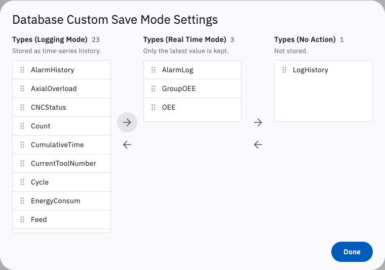
- The default storage mode is User Defined: click the Settings button on the right and use the “Database Custom Save Mode Settings” dialog to put each individual task into Log mode or Real Time mode. In the dialog, the left column is Types (Logging Mode), the middle column is Types (Real Time Mode) and the right column is Types (No Action) (not recorded). Drag an interface with the mouse into the mode you want, or click the left and right arrow buttons to move every interface on one side across to the other. Click anywhere outside the dialog to close it, then click Save on the page to store your custom settings. By default Alarm, Machine OEE and Group OEE are in Real Time mode and all other data is in Log mode.
- Data Retention Period (h) is how long data is kept in the database, in hours. If it is set to x, the gateway runs a scheduled database cleanup after start-up and automatically deletes data older than x hours. The default is 0, which keeps all data.
- With Use Local Time on, data is written using the local time of the time zone set in 3.12. Settings; otherwise UTC is used.
- Enable Primary Key adds a primary key column to every table in the database.
- With Write on Value Change on, the automatic collection tasks enabled in the machine task settings and group task settings only write a result when the collected value has changed.
3.6.5. Gateway File Server Settings
Section titled “3.6.5. Gateway File Server Settings”Turn on the Enable switch to start the gateway file server. The gateway file server is a file server created locally on the gateway that machines can reach over FTP or as a shared folder. Once it is running, the File Server Type option in 3.3.1.3. DNC Settings can be set to “Gateway File Server”.
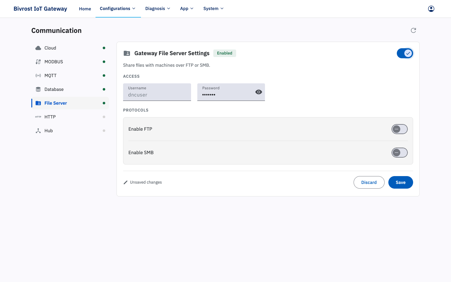
The username and password are shared by FTP and the shared folder. Both default to dnc_user. At present only the password can be changed.
Turn on Enable FTP to allow the gateway file server to be reached over FTP. The FTP address is:
ftp://iotgw or ftp://<gateway-IP>Under the FTP home directory each machine has its own folder, named after the machine’s IP address.
Turn on Enable SMB to allow the gateway file server to be reached as a shared folder. Each machine has its own shared folder, named after the machine’s IP address. The shared folder address is:
\\iotgw\<machine-IP> or \\<gateway-IP>\<machine-IP>3.6.6. HTTP Settings
Section titled “3.6.6. HTTP Settings”Turn on the Enable switch to start the HTTP service.
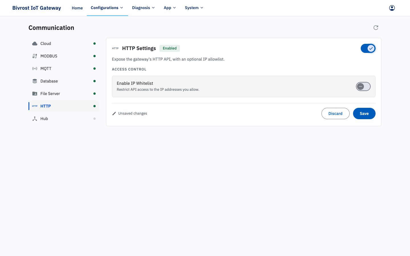
With Enable IP Whitelist on, all API requests except those with valid JWT authentication are restricted to whitelisted IP addresses. That is, the login endpoint is not restricted by the whitelist, and requests authenticated with a JWT after login skip the whitelist check; requests authenticated with a SecretKey must still pass the whitelist check. The Whitelist can hold several IP addresses, separated by “;”.
3.6.7. Hub Settings
Section titled “3.6.7. Hub Settings”Turn on the Enable switch to start the Hub service. A Hub server is used to reach the gateway’s interfaces remotely, so that configuration can be changed remotely and gateways on different sites can exchange data. Contact support to have one deployed.
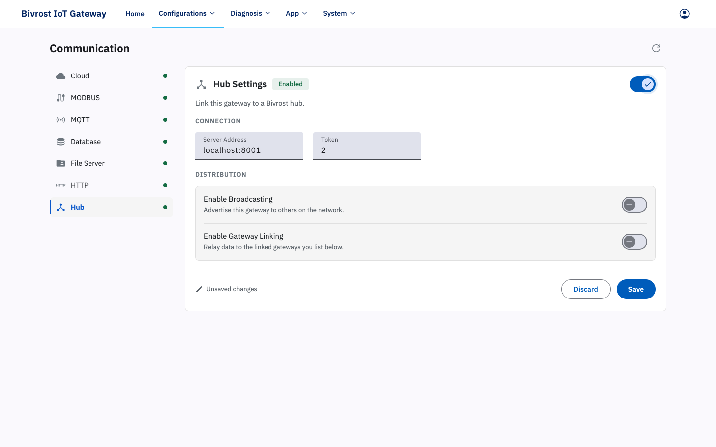
After completing Hub Settings, saving, restarting the service and confirming that the gateway is connected to the Hub, replace the gateway address in the HTTP request URL with the Hub server address and add an AccessToken request header whose value is the gateway token entered in Token on this page. See 5.1.1. Forwarding Requests Through the Cloud Platform or Hub for instructions and an example.
- Enter the Hub server address in Broker Address.
- Enter the token the Hub server has assigned to the gateway in Token.
- With Enable Broadcasting on, the gateway broadcasts data through the cloud platform to the other gateways on that platform.
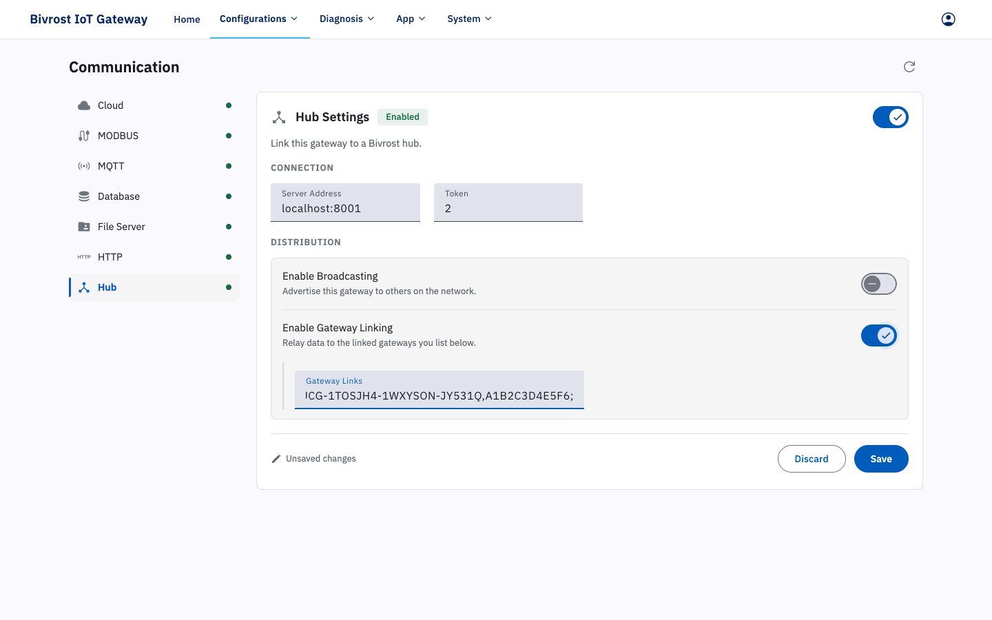
- With Enable Gateway Linking on, the gateway receives data broadcast by other gateways through the Hub server. Add the UID and token of each gateway you want to link to under Gateway Links, in the following format:
UID,token;Separate multiple linked gateways with ;.
3.6.8. MCP Settings
Section titled “3.6.8. MCP Settings”Turn on the Enable switch and click Save to start the MCP service. The MCP (Model Context Protocol) server exposes machine data, data analysis and gateway status as “tools” for MCP-capable AI clients (such as Claude Code and Claude Desktop), so machines can be queried in natural language without calling the interfaces by hand.
Endpoint shows this gateway’s MCP server address (for example http://192.168.100.1/mcp), for use in the MCP client’s configuration. It is read-only.
The MCP service is disabled by default; while it is off, that address returns HTTP 404. It currently exposes 33 read-only tools — anything involving writes, machine control or program transfer has no MCP tool. Authentication and access control follow the HTTP interface settings (secret keys, IP whitelist, authorized APIs) and need no separate configuration on this page. For the full tool list, the authentication methods and client configuration examples, see 9. MCP Service.