
11.2. Command Format
11.2.1. PLC Data Task
Section titled “11.2.1. PLC Data Task”A PLC data task has the format below. Separate multiple reads with “;”.
Area,Start Address[|Tag],Data Count,Data Type[,Precondition,Task Interval,Post-processing];Area, Start Address, Data Count and Data Type are mandatory — together they define where the data comes from and what shape it has. Tag, Precondition, Task Interval and Post-processing are optional.
- Tag identifies the data in MQTT, database and other communication channels. If you do not set one, the gateway assigns it automatically from the task order and the data length.
- Precondition is the precondition for this command. It is evaluated first, and the command runs only if the condition is met; if it is not set, the command always runs. It works exactly like 3.3.1.2.1. Precondition. For the syntax, see 4.2.2. Precondition.
- Task Interval is the interval for this command. If it is not set, the gateway uses the matching interval from 3.5.1. Machine Task Interval Settings and 3.5.2. Group Task Interval Settings. For the syntax, see 4.2.3. Task Interval.
- Post-processing may appear more than once. Each post-processing expression transforms data returned by this task or by another task and publishes the result under a new tag. See 4.2.4. Post-processing.
Taking [CNC]Fanuc [Oi-F] as an example:
R,0,9,Byte;R,100|Data2,6,Byte,$COND$CNCStatus_cncStatus = "AUTO_RUN"$COND$;R,200|rawData0,1,Byte,$INTERVAL$1000$INTERVAL$,$POST$___PLC_TrawData0___[0]>0$POST$|Heartbeat;R,0,9,Bytereads 9 values of type Byte starting at PLC address R0 (R0 included), with no tag set.R,100|Data2,6,Bytereads 6 values of type Byte starting at PLC address R100 (R100 included), tagged “Data2”, with the preconditionCNCStatus_cncStatus = "AUTO_RUN"— that is, only while the machine is in automatic operation. For more on preconditions, see 4.2.2. Precondition.R,200|rawData0,1,Bytereads one value of type Byte at PLC address R200, tagged “rawData0”.$INTERVAL$1000$INTERVAL$sets the interval for this command to 1000 milliseconds.$POST$___PLC_TrawData0___[0]>0$POST$|Heartbeatis a post-processing expression and its tag: it tests whether the value read into rawData0 is greater than 0 and publishes the result under the tag “Heartbeat”. For more on post-processing, see 4.2.4. Post-processing.
Taking [PLC]Simatic [S300] as an example:
DB1,1,3,Byte;DB10,100|FloatData,10,Float;DB1,1,3,Bytereads 3 values of type Byte starting at PLC address DB1.1 (DB1.1 included), with no tag.DB10,100|FloatData,10,Floatreads 10 values of type Float starting at PLC address DB10.100 (DB10.100 included), tagged “FloatData”.
Some devices support reading data by variable name. Taking [PLC]Allen-Bradley [1783] as an example:
$TAG$|name=AB.C[0],,8,Float;$TAG$|name=AB.C[0],,8,Float reads elements 0 through 7 of the Float array held in the PLC variable named AB.C, addressed by tag. Note that the field corresponding to Start Address is left empty in this form.
For a fuller description of Area, Start Address, Data Count, Data Type and the other parameters, see the request-parameter section of 5.5.1.20. readPlcData (Read PLC Data).
Consult the device manual or contact the device manufacturer to obtain the area and address of the target PLC data and the type of the target data.
11.2.2. Precondition
Section titled “11.2.2. Precondition”A precondition sets the prerequisite for running a task: the collection task runs only when the condition you set is met. If it is left blank, there is no precondition and the task runs directly.
For non-PLC data tasks you set the precondition in 3.3.1.2.1. Precondition. For PLC data tasks you add a precondition command inside the command itself, in this format:
$COND$Precondition$COND$A precondition is essentially a logical test. A single precondition command looks like this:
a > 100 // variable a is greater than 100b < 50.0f // variable b is less than 50.0fc = "AUTO_RUN" // variable c is the string "AUTO_RUN"d <> 0 // variable d is not equal to 0e >= 12.34f // variable e is greater than or equal to 12.34ff <= g // variable f is less than or equal to variable gnot h in (1,2,3) // variable h is not one of (1,2,3)Several precondition commands can be combined with and, or and (), for example:
a > 100 and (b < 50.0f or c = "AUTO_RUN")The variables currently available for logical tests are <type>_<tag> and prev_<type>_<tag>, where <type> is the data class, <tag> is the data tag, and prev refers to the previous value of the data. For details on <type> and <tag>, see 4.2. Data Description.
11.2.3. Task Interval
Section titled “11.2.3. Task Interval”The task interval sets the interval for a specific task. If it is not set, the gateway uses the matching interval from 3.5.1. Machine Task Interval Settings and 3.5.2. Group Task Interval Settings. The format is:
$INTERVAL$Interval$INTERVAL$Interval is a number, in milliseconds.
11.2.4. Post-processing
Section titled “11.2.4. Post-processing”Post-processing commands let you transform the raw data you collect. Two kinds are currently available:
11.2.4.1. $DA$ Direct Access
Section titled “11.2.4.1. $DA$ Direct Access”$DA$ takes a single value at a given position out of the data read by the command to its left and publishes it under a given tag. It cannot perform calculations, but it lets you merge PLC tasks whose addresses are adjacent, reducing the number of PLC tasks and improving execution efficiency. For example:
R,2036|count,5,Int32,$DA$0$DA$|Part Count,$DA$3$DA$|Part Count-Good,$DA$4$DA$|Part Count-Reject;This reads 5 Int32 values starting at R2036, giving an array of length 5. $DA$ then takes element 0 and tags it Part Count, takes element 3 and tags it Part Count-Good, takes element 4 and tags it Part Count-Reject, and uploads these three values.
If a $DA$ tag is not specified, the default tag is <raw data tag>_<number>, where the number is the position given to $DA$. Had the example above set no tags, the three values would default to count_0, count_3 and count_4.
11.2.4.2. $POST$ Post-processing
Section titled “11.2.4.2. $POST$ Post-processing”$POST$ performs calculations, comparisons and similar processing on one or more values that have already been collected, and uploads the result.
The gateway keeps the most recent task data as variables. Variables belonging to the same machine can be referenced inside $POST$ using the format ___VariableName___ — three underscores before and after the variable name to mark its start and end. Take ___PLC_TrawData2_data___: PLC is the data type, T is the abbreviation for tag, rawData2 is the data’s tag, and data is a field of the PLC data class, which is an array. Together the variable name is PLC_TrawData2_data, meaning the PLC data class, with tag T set to rawData2 and field data — that array. Adding three underscores at each end per the variable format gives ___PLC_TrawData2_data___. For details on data classes, data tags and fields, see 4.2. Data Description. This mechanism lets you use, inside $POST$, any data collected by any enabled task.
The gateway keeps at most the two most recent sets of task data. The most recent set is addressed as described above; for the set before it, add the prefix prev_ to the variable name, for example ___prev_PLC_TrawData2_data___.
Example 1:
R,2000|rawData2,1,Byte,$INTERVAL$900$INTERVAL$,$POST$(___PLC_TrawData2_data___[0] and 1>0$POST$|Heartbeat;Every 900 milliseconds, one Byte is read starting at R2000, giving an array of length 1 stored under the tag rawData2. Inside $POST$, the value at position 0 of that rawData2 array is taken; if it is greater than 0 the result is True, otherwise False, and the result is uploaded under the tag Heartbeat.
You can use several $POST$ expressions in a single PLC data task to perform different calculations, as in Example 2 and Example 3.
Example 2:
R,3012|rawData3,3,Int32,$POST$___PLC_TrawData3_data___[0]*0.1f$POST$|Tool-to-Tool Change Time,$POST$___PLC_TrawData3_data___[1]*0.1f$POST$|Total Tool Change Time,$POST$___PLC_TrawData3_data___[2]*0.1f$POST$|Tool Machining Time;The raw values are Int32 in units of [0.1 s]; each is multiplied by 0.1f to convert it to a Float in units of [s].
Example 3:
R,2003|rawData4,1,Byte,$POST$(___PLC_TrawData4_data___[0] and (1<<4))>0$POST$|Data Ready,$POST$(___PLC_TrawData4_data___[0] and (1<<5))>0$POST$|Part Data Ready,$POST$(___PLC_TrawData4_data___[0] and (1<<6))>0$POST$|Part OK,$POST$(___PLC_TrawData4_data___[0] and (1<<7))>0$POST$|Part NG;The raw value is a single Byte in which each bit has a different meaning. Bit 4 of the Byte is taken (bit 0 being the least significant bit) and compared with 0, giving True or False, tagged Data Ready; bit 5 is tested for greater than 0 and tagged Part Data Ready; bit 6 is tested and tagged Part OK; bit 7 is tested and tagged Part NG.
Besides the usual +, -, *, /, and, or, <, >, = operators, the gateway also supports nested if tests. Example 4 derives the current status from a PLC value.
Example 4:
D,0|rawData0,1,Int16,$POST$if(___PLC_TrawData0_data___[0] = 1, "AUTO_RUN",if(___PLC_TrawData0_data___[0] = 2,"MANUAL_HOLD",if(___PLC_TrawData0_data___[0] = 4, "EMERGENCY", "WAIT")))$POST$|Machine Status,$POST$if(___PLC_TrawData0_data___[0] = 4, "ALARM",if(___PLC_TrawData0_data___[0] = 5, "ALARM", "NO_ALARM"))$POST$|Alarm Status;The value of D0 represents the state of the machine. D0=1: automatic operation; D0=2: paused; D0=4: emergency stop; D0=5: alarm present; any other value of D0: Wait. D0=4 and D0=5 both count as an alarm state.
11.2.4.3. $POST$ Post-processing Functions
Section titled “11.2.4.3. $POST$ Post-processing Functions”Inside a $POST$ command you can call methods on .NET static members such as Encoding, Enumberable, BitConverter and Math.
The following functions extract a sub-array from a source array; each name applies to arrays holding the corresponding element type:
PGetSubBytes,PGetSubSBytes,PGetSubChars,PGetSubShorts,PGetSubUShorts,PGetSubInts,PGetSubUInts,PGetSubFloats,PGetSubLongs,PGetSubULongs,PGetSubDoubles;| Input | Type | Description |
|---|---|---|
| source | Object[] | (Required) The source array |
| startIndex | Int32 | (Required) The start position |
| count | Int32 | (Required) The number of elements |
| isReverse | Bool | Whether to reverse the order; False by default |
| isSwap | Bool | Whether to swap elements in pairs; False by default |
| step | Int32 | The step, i.e. the gap between the elements taken; 0 by default |
These functions build a sub-array out of the source array: they start at the element at the start position, skip the specified number of elements (0 by default) to reach the next one, and continue until the specified number of elements has been collected. The sub-array is then reversed if you asked for it (off by default), and finally its elements are swapped in pairs if you asked for it (off by default).
PGetSubBytes example:
source = {0x01, 0x02, 0x30, 0x40, 0x66, 0x88},startIndex = 1,count = 3,isReverse = True,isSwap = True,step = 1,Three elements are taken starting at position 1 with a gap of 1, giving {0x02, 0x40, 0x88}. Reversing them gives {0x88, 0x40, 0x02}. They are then swapped in pairs — note that the length 3 is odd, so the last element takes no part in the pairwise swap. The result is {0x40, 0x88, 0x02}.
Functions of this kind suit cases where a single PLC data task reads a large block of data from which each individual value is then parsed out and reported separately as a post-processing result. Handling it this way improves communication efficiency enormously. In the example below, 198 Bytes are read from a Siemens PLC in one go and converted, according to their address offsets, into String / Bool / UInt16 / Float / UInt32 and other types.
DB500,0|rawData0,198,Byte,$POST$UTF8.GetString(PGetSubBytes(___PLC_TrawData0_data___, 0, 8))$POST$|Production Line,$POST$UTF8.GetString(PGetSubBytes(___PLC_TrawData0_data___, 8, 6))$POST$|Process No,$POST$UTF8.GetString(PGetSubBytes(___PLC_TrawData0_data___, 14, 1))$POST$|Machine No,$POST$UTF8.GetString(PGetSubBytes(___PLC_TrawData0_data___, 18, 20))$POST$|System Device No,$POST$ToUInt16(PGetSubBytes(___PLC_TrawData0_data___, 38, 2, true), 0)$POST$|Device Status,$POST$(___PLC_TrawData0_data___[40] and 1)>0$POST$|Device On,$POST$(___PLC_TrawData0_data___[40] and (1<<1))>0$POST$|Device Off,$POST$(___PLC_TrawData0_data___[40] and (1<<3))>0$POST$|Emergency,$POST$(___PLC_TrawData0_data___[40] and (1<<4))>0$POST$|Device Fault Stop,$POST$(___PLC_TrawData0_data___[40] and (1<<6))>0$POST$|Other Mode,$POST$(___PLC_TrawData0_data___[40] and (1<<7))>0$POST$|Pass-Through Mode,$POST$(___PLC_TrawData0_data___[41] and 1)>0$POST$|Auto Mode,$POST$(___PLC_TrawData0_data___[41] and (1<<1))>0$POST$|Non-Auto Mode,$POST$(___PLC_TrawData0_data___[41] and (1<<2))>0$POST$|Cycle Start,$POST$(___PLC_TrawData0_data___[41] and (1<<3))>0$POST$|Cycle Stop,$POST$(___PLC_TrawData0_data___[41] and (1<<4))>0$POST$|Special Mode,$POST$(___PLC_TrawData0_data___[41] and (1<<5))>0$POST$|Dry Run,$POST$(___PLC_TrawData0_data___[41] and (1<<6))>0$POST$|Material Jam,$POST$(___PLC_TrawData0_data___[41] and (1<<7))>0$POST$|Waiting for Material,$POST$(___PLC_TrawData0_data___[42] and 1)>0$POST$|In Production,$POST$(___PLC_TrawData0_data___[42] and (1<<1))>0$POST$|Device Alarm,$POST$(___PLC_TrawData0_data___[42] and (1<<2))>0$POST$|Safety Door Open,$POST$(___PLC_TrawData0_data___[42] and (1<<3))>0$POST$|Safety Door Closed,$POST$(___PLC_TrawData0_data___[44] and 1)>0$POST$|Station 1 Load Request,$POST$(___PLC_TrawData0_data___[44] and (1<<1))>0$POST$|Station 1 Unload Request,$POST$(___PLC_TrawData0_data___[44] and (1<<2))>0$POST$|Station 1 Part Present,$POST$(___PLC_TrawData0_data___[46] and 1)>0$POST$|Station 2 Load Request,$POST$(___PLC_TrawData0_data___[46] and (1<<1))>0$POST$|Station 2 Unload Request,$POST$(___PLC_TrawData0_data___[46] and (1<<2))>0$POST$|Station 2 Part Present,$POST$(___PLC_TrawData0_data___[48] and 1)>0$POST$|Station 3 Load Request,$POST$(___PLC_TrawData0_data___[48] and (1<<1))>0$POST$|Station 3 Unload Request,$POST$(___PLC_TrawData0_data___[48] and (1<<2))>0$POST$|Station 3 Part Present,$POST$(___PLC_TrawData0_data___[50] and 1)>0$POST$|Station 4 Load Request,$POST$(___PLC_TrawData0_data___[50] and (1<<1))>0$POST$|Station 4 Unload Request,$POST$(___PLC_TrawData0_data___[50] and (1<<2))>0$POST$|Station 4 Part Present,$POST$(___PLC_TrawData0_data___[52] and 1)>0$POST$|Station 5 Load Request,$POST$(___PLC_TrawData0_data___[52] and (1<<1))>0$POST$|Station 5 Unload Request,$POST$(___PLC_TrawData0_data___[52] and (1<<2))>0$POST$|Station 5 Part Present,$POST$(___PLC_TrawData0_data___[54] and 1)>0$POST$|Load Station Load Request,$POST$(___PLC_TrawData0_data___[54] and (1<<1))>0$POST$|Load Station Unload Request,$POST$(___PLC_TrawData0_data___[54] and (1<<2))>0$POST$|Load Station Part Present,$POST$(___PLC_TrawData0_data___[56] and 1)>0$POST$|Unload Station Load Request,$POST$(___PLC_TrawData0_data___[56] and (1<<1))>0$POST$|Unload Station Unload Request,$POST$(___PLC_TrawData0_data___[56] and (1<<2))>0$POST$|Unload Station Part Present,$POST$ToUInt16(PGetSubBytes(___PLC_TrawData0_data___, 58, 2, true), 0)$POST$|Axis Position_TY,$POST$ToUInt16(PGetSubBytes(___PLC_TrawData0_data___, 60, 2, true), 0)$POST$|Axis Position_TZ1,$POST$ToUInt16(PGetSubBytes(___PLC_TrawData0_data___, 62, 2, true), 0)$POST$|Axis Position_TZ2,$POST$ToUInt16(PGetSubBytes(___PLC_TrawData0_data___, 64, 2, true), 0)$POST$|Axis Position_TX1,$POST$ToUInt16(PGetSubBytes(___PLC_TrawData0_data___, 66, 2, true), 0)$POST$|Axis Position_TX2,$POST$(___PLC_TrawData0_data___[68] and 1)>0$POST$|Gripper 1 Clamped,$POST$(___PLC_TrawData0_data___[68] and (1<<1))>0$POST$|Gripper 2 Clamped,$POST$ToSingle(PGetSubBytes(___PLC_TrawData0_data___, 70, 4, true), 0)$POST$|Cycle Time (excluding wait),$POST$(___PLC_TrawData0_data___[74] and 1)>0$POST$|Data Ready,$POST$UTF8.GetString(PGetSubBytes(___PLC_TrawData0_data___, 76, 28))$POST$|Part QR Code,$POST$UTF8.GetString(PGetSubBytes(___PLC_TrawData0_data___, 104, 10))$POST$|RFID_Process No,$POST$UTF8.GetString(PGetSubBytes(___PLC_TrawData0_data___, 114, 2))$POST$|RFID_Spindle No,$POST$ToUInt16(PGetSubBytes(___PLC_TrawData0_data___, 116, 2, true), 0)$POST$|RFID_Part Status,$POST$UTF8.GetString(PGetSubBytes(___PLC_TrawData0_data___, 118, 2))$POST$|RFID_Inspection Info,$POST$UTF8.GetString(PGetSubBytes(___PLC_TrawData0_data___, 120, 12))$POST$|Machining Time,$POST$ToUInt32(PGetSubBytes(___PLC_TrawData0_data___, 130, 4, true), 0)$POST$|Alarm Code 1,$POST$ToUInt32(PGetSubBytes(___PLC_TrawData0_data___, 134, 4, true), 0)$POST$|Alarm Code 2,$POST$ToUInt32(PGetSubBytes(___PLC_TrawData0_data___, 138, 4, true), 0)$POST$|Alarm Code 3,$POST$ToUInt32(PGetSubBytes(___PLC_TrawData0_data___, 142, 4, true), 0)$POST$|Alarm Code 4,$POST$ToUInt32(PGetSubBytes(___PLC_TrawData0_data___, 146, 4, true), 0)$POST$|Alarm Code 5,$POST$ToUInt32(PGetSubBytes(___PLC_TrawData0_data___, 150, 4, true), 0)$POST$|Alarm Code 6,$POST$ToUInt32(PGetSubBytes(___PLC_TrawData0_data___, 154, 4, true), 0)$POST$|Alarm Code 7,$POST$ToUInt32(PGetSubBytes(___PLC_TrawData0_data___, 158, 4, true), 0)$POST$|Alarm Code 8,$POST$ToUInt32(PGetSubBytes(___PLC_TrawData0_data___, 162, 4, true), 0)$POST$|Alarm Code 9,$POST$ToUInt32(PGetSubBytes(___PLC_TrawData0_data___, 166, 4, true), 0)$POST$|Alarm Code 10,$POST$UTF8.GetString(PGetSubBytes(___PLC_TrawData0_data___, 170, 28))$POST$|Station 1 Part QR Code;PToStringArray
PToStringArray(item)Converts an input of any type into a string array: for an array or collection, the output holds the ToString() result of each element (a null element becomes an empty string); for a single value, the output is a one-element array holding that value’s ToString() result.
GetActiveBits
GetActiveBits(bytes, offset[, bytes2, offset2, ...])| Input | Type | Description |
|---|---|---|
| bytes | Byte[] | (Required) The Byte array to inspect |
| offset | Int32 | (Required) Offset added to each index |
Finds every Bit set to 1 in the Byte array and outputs a string array of “index + offset”. Bit j (counted from the least significant bit) of Byte i has index i×8+j, with both i and j starting at 0. Arguments must come in pairs; when several pairs are passed, their results are appended in order. This is typically used to turn a PLC alarm bit area into a list of alarm numbers.
For example, with bytes = {0x05, 0x80} and offset = 100, bits 0 and 2 of Byte 0 and bit 7 of Byte 1 are set, so the output is {"100", "102", "115"}.
11.2.4.4. $MOCK$ Mock Task
Section titled “11.2.4.4. $MOCK$ Mock Task”A $MOCK$ task returns the requested number of dummy values of the requested type. The returned values carry no real meaning; they exist only for a few special situations. Post-processing cannot stand on its own — it must follow the mandatory part of a PLC task. In some cases, however, the post-processing needs a different interval from the data read, or for other reasons has to be set up as a task of its own. A $MOCK$ task covers those cases.
$MACRO$,500|macro1_500_515,16,Double,$DA$0$DA$,$DA$1$DA$,$DA$2$DA$,$DA$3$DA$,$DA$4$DA$,$DA$5$DA$,$DA$6$DA$,$DA$7$DA$,$DA$8$DA$,$DA$9$DA$,$DA$10$DA$,$DA$11$DA$,$DA$12$DA$,$DA$13$DA$,$DA$14$DA$,$DA$15$DA$;$MOCK$,1,1,Byte,$INTERVAL$60000$INTERVAL$,$POST$(___PLC_Tmacro1_500_515_8_pDouble___ - ___PLC_Tmacro1_500_515_0_pDouble___)<=10$POST$|Cutoff Tool Life Low;Here the first task reads machine macro variables 500 to 515 at the default interval of once every 5 seconds. The second task runs once a minute, subtracts macro variable 500 from macro variable 507 as read by the first task, and tests whether the difference is less than or equal to 10. The result, True or False, is uploaded under the tag “Cutoff Tool Life Low”.
11.2.5. External PLC Data Task
Section titled “11.2.5. External PLC Data Task”The gateway can collect data from equipment around the machine by adding an external PLC.
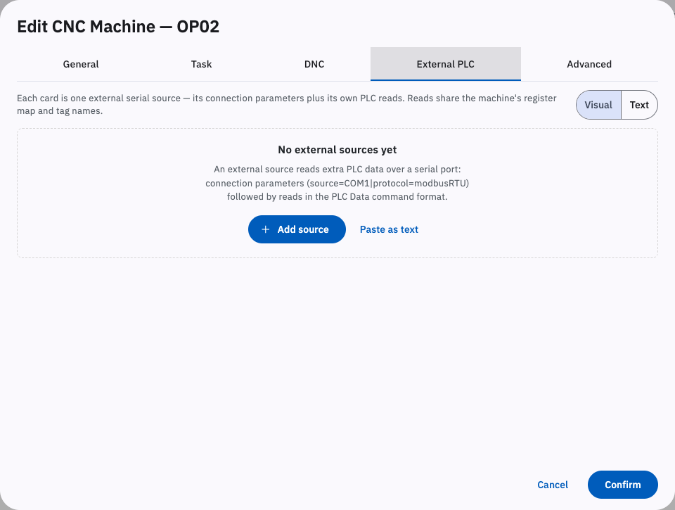
The command has three parts: the parameters of the external PLC, the parameters of the communication protocol, and the PLC read commands.
Parameters of the external PLC:
| Parameter | Description |
|---|---|
| source | Data source. Allowed values: COM1, COM2, COM3 and so on, corresponding to serial ports 1-3 on the gateway. |
| protocol | Communication protocol. Allowed value: modbusRTU. |
| baudRate | Serial baud rate. Default 9600. |
| parity | Parity bit. Allowed values: none, odd, even. Default none. |
| dataBits | Data bits. Default 8. |
| stopBits | Stop bits. Allowed values: 1, 1.5, 2. Default 1. |
Supported communication protocols:
modbusRTU
| Parameter | Description |
|---|---|
| slaveID | Slave ID. Default 1. |
| plcAddresses | Whether the addresses are PLC addresses. Allowed values: false, true. Default false. When true, Modbus addresses start at 1; when false, Modbus addresses start at 0. |
| encoding | Encoding. Default GBK. |
| bit32TypeFormat | 32-bit type format (Byte(4) Order). Allowed values: ABCD, CDAB, BADC, DCBA. Default DCBA. |
| bit64TypeFormat | 64-bit type format (Byte(8) Order). Allowed values: ABCDEFGH, GHEFCDAB, BADCFEHG, HGFEDCBA. Default HGFEDCBA. |
For the PLC read commands, see 4.2.1. PLC Data Task.
Example:
With a temperature sensor on the machine’s serial port 1 and a smart power meter on serial port 2, you can set up two external PLC task commands to collect the machine’s temperature and energy consumption.
source=COM1|protocal=modbusRTU;4x,0,1,Int16;source=COM2|protocal=modbusRTU|baudRate=14400|encoding=ASCII;4x,0,1,Int16;4x,10,2,Int32;Separate different data sources with a line break.
- First line: over gateway serial port 1, using the modbusRTU protocol, read 1 Int16 from area 4x starting at address 0.
- Second line: over gateway serial port 2, using the modbusRTU protocol with the baud rate set to 14400 and the encoding set to ASCII, read 1 Int16 from area 4x starting at address 0, and 2 Int32 starting at address 10.
11.2.6. External Machines
Section titled “11.2.6. External Machines”By adding external machines you can bring machines belonging to other gateways into a group on this gateway. You must first link the other gateway in Cloud Settings or Hub Settings.
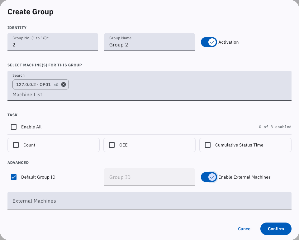
The command format is:
UID,MachineID[|countMultiplier=COUNTMULTIPLIER|name=NAME,...];...UID is the UID of the other, already linked gateway; MachineID is the machine number of the machine on that gateway; countMultiplier is the Count Multiplier, optional, 0 by default; name is the Machine Name, optional, the same as MachineID by default. Separate multiple external machines with “;”. For example:
iotgw1,1;iotgw2,100010|countMultiplier=1|name=Machining Center 10;11.2.7. Protected API and Authorized APIs
Section titled “11.2.7. Protected API and Authorized APIs”API commands are used to configure protected APIs and authorized APIs.
The command format is:
Command Type,API address prefix or API address;An API address is the part after “/api” of the address of each interface in 2.5. Data Read/Write Interfaces through 5.10. Gateway Function Interfaces. Separate multiple commands with “;”.
There are two command types: prefix match and exact match.
1. Prefix match covers every API address that begins with the given prefix:
prefix,/cnc;prefix,/analysis;prefix,/config;Here prefix denotes a prefix match; /cnc covers every API whose address starts with /cnc, that is 5.5. Data Read/Write Interfaces and 5.6. File Management Interfaces; /analysis covers every API whose address starts with /analysis, that is 5.7. Data Analysis Interfaces; /config covers every API whose address starts with /config, that is 5.9. Gateway Configuration Interfaces.
2. Exact match names the address of one specific API:
exact,/cnc/writeOffsetData;exact,/cnc/writePlcData;Here exact denotes an exact match; /cnc/writeOffsetData is the address of the interface that writes tool offset data, see 2.5.1.14. writeOffsetData (Write Offset Data); /cnc/writePlcData is the address of the interface that writes PLC data, see 2.5.1.19. writePlcData (Write PLC Data).